Will There Be Lights?
This is the third part of my blog series reporting the creation of a set of programmable party lights. In the previous post I covered the design of the circuit board for the LEDs. In this article I’ll discuss the building and testing of the boards. Enjoy!
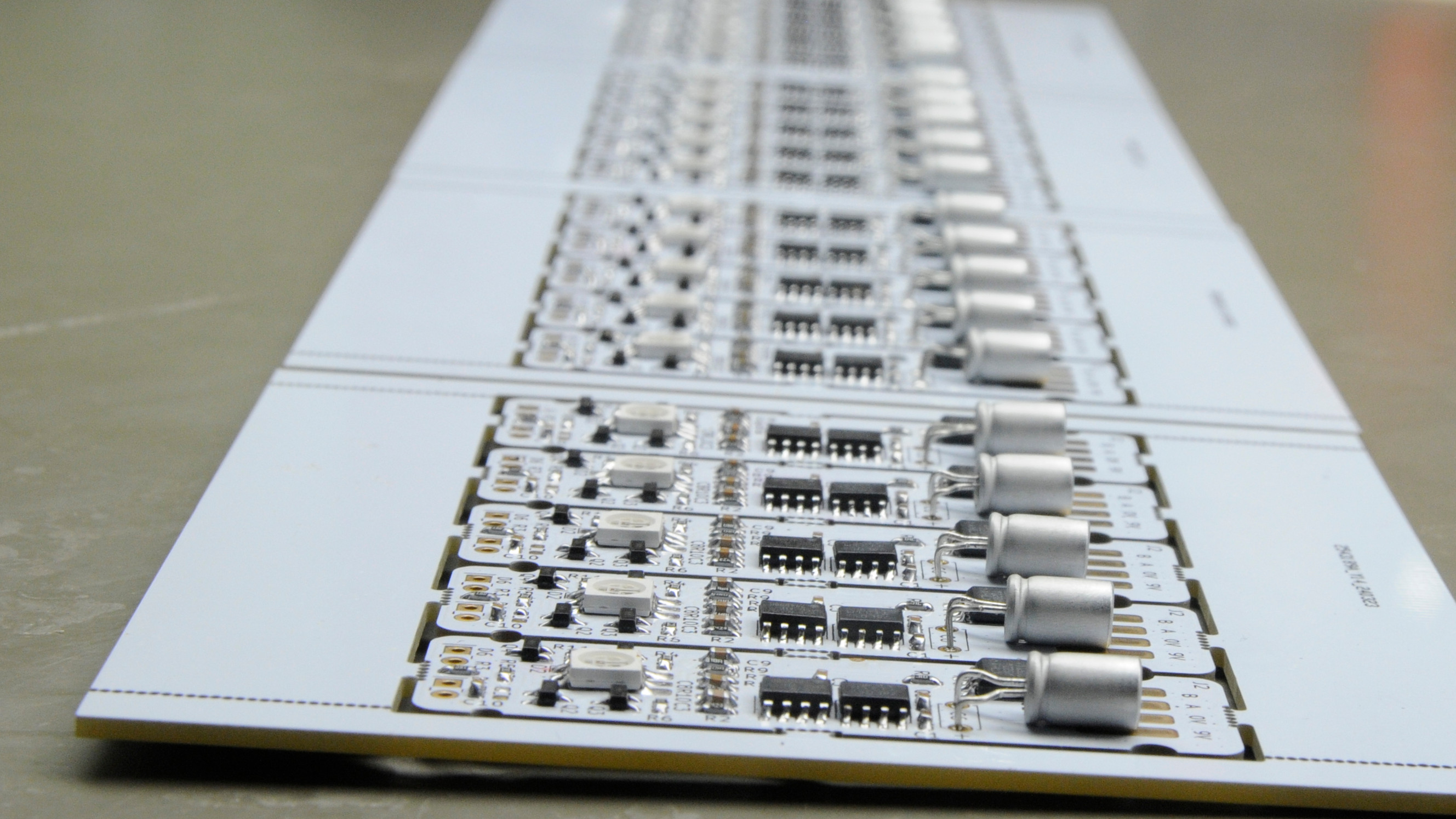
The Boards Are In!
I always get thoroughly excited when a board of my own design gets delivered. That marvelous moment at which something that has thus far been a concept on a computer screen turns up in its physical form. Even if all components still lay in plastic bags on the bench.
The boards have been panelized with the Kikit panelization plug-in for KiCad which I can recommend to anyone! I had hoped that I would have gotten the discount that JLC PCB offer when you order boards in their default 100x100mm form factor. Unfortunately, you won’t get the special offer if they detect your boards are in a panel. It still pays to have tiny boards like this panelized anyway, as it makes the soldering so much easier.
The boards all seemed to be in perfect order and ready to be populated. The parts arrived a few weeks before I placed the order for the boards because I like to check the footprints on a printed (on paper) version of the board before actually ordering. It’s very painful to have to scrap your brand new boards because you got a critical footprint wrong.
Soldering. A Lot…
It’s great to design a project and even more so to see it come to fruition. Somewhere in between the two, the thing has to built which generally is fun too. I did learn that there is a certain limit beyond which soldering boards becomes so tedious it becomes a burden. Twenty-five is definitely above that limit.
The soldering was actually production work and literally took hours. I’ve done a fair bit of soldering in my life bit I’m not exactly fast. Each LED board took me half an our to make. At some point I felt like a human pick and place machine. Not to mention a human fume extractor and I might have poisoned myself with the flux fumes.
Talking about flux, I’m not one of those guys who solder surface mount parts perfectly in no time. (Not to mention perfectly and with unleaded solder; those folks are nothing short of magicians). What I’ve learned though, is that flux is the solution to most of your soldering woes. Use it liberally and surface mount parts will stick.
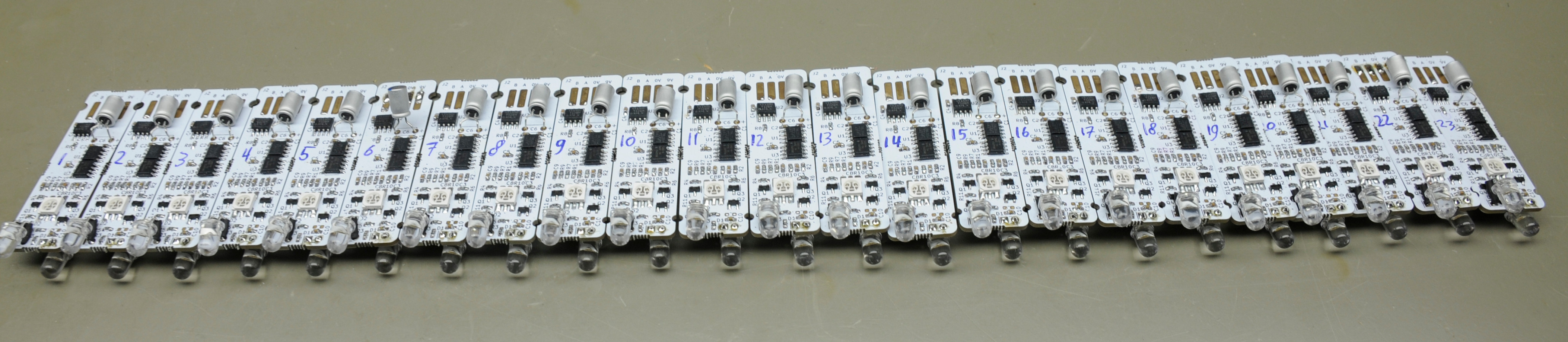
It took a lot of time and perseverance, but in the end I succeeded and found myself admiring twenty-five neatly panelized, populated boards, ready to test.
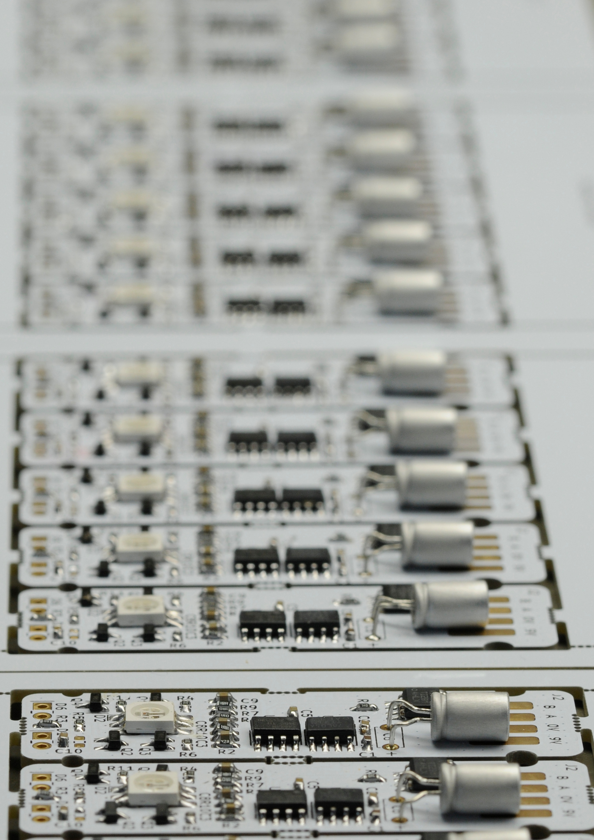 A dizzying number of boards
Rigging Up a Jig
As mentioned in part two of this series, I wanted to use a test jig to streamline the programming and testing of the boards. The plan was to only touch each assembled board just once. Just pop it into the jig, check the voltage supply, flash the firmware, do a functional test and be done with it.
In reality it didn’t go that easily.
I 3D printed the jig and mounted it on a piece of perfboard. The first hurdle was getting the pogo pins to align properly with the LED board in the jig. The pogo pins I used are through hole parts, but they require a smaller hole diameter than that of standard perfboard. So they all stood at odd angles and didn’t make contact with the board. It took a lot of testing and re-soldering to get right. The second issue was board alignment. The jig is slightly larger that the board outline. This prevents the boards from having to be jammed into the jig with too much force. The extra wiggle room came with the unwanted side effect of the - already badly aligned - pogo pins to sometimes land outside of the test pads. Lastly, the boards wouldn’t fit if the white LEDs were mounted. I didn’t feel like printing another version of the jig, so I ended up with two LEDs propped onto a pin header that would temporarily slide into the LED holes during the test.
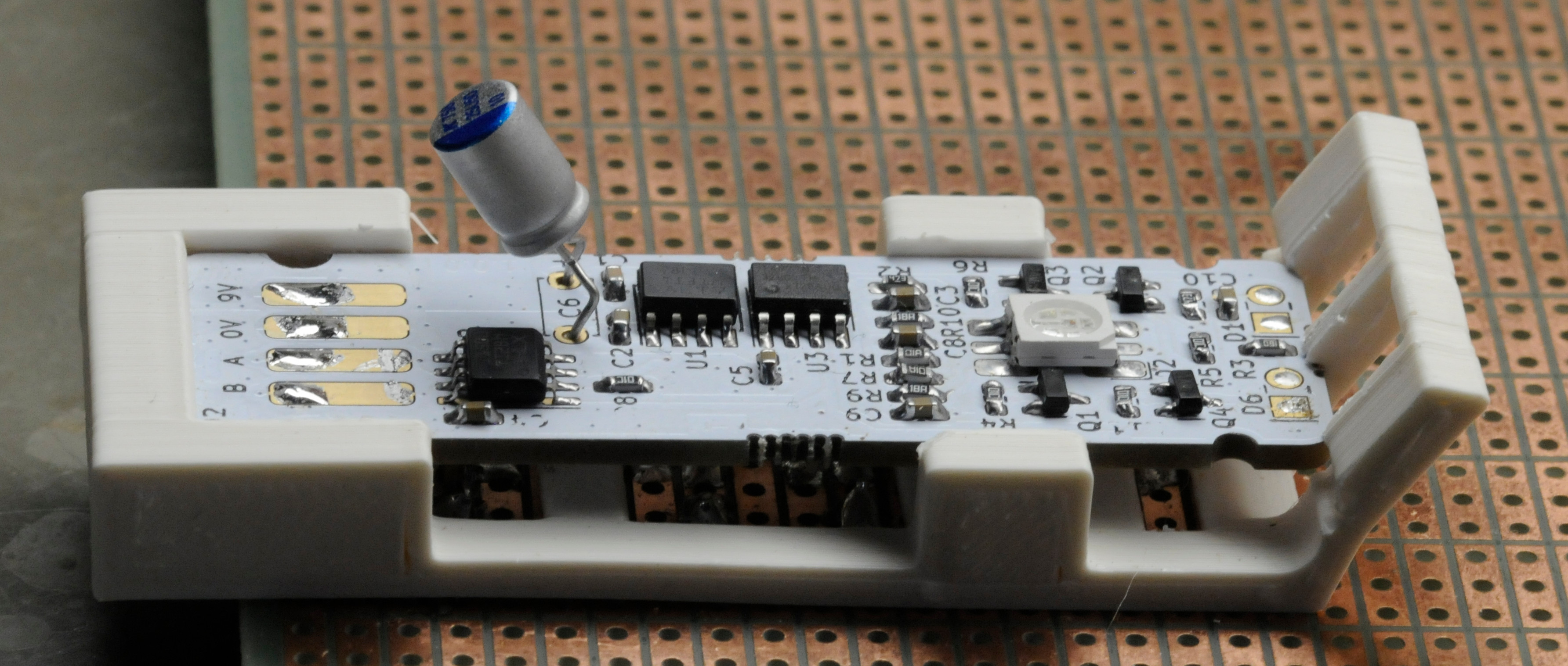 Wonky test jig.
The Attiny comes with a one-wire programming interface by the the name of UPDI. This is a simple serial interface that uses the reset pin. There’s no special tooling required: a USB to UART converter combined with a single resistor suffices to connect to the device. The chip can be programmed with the open source pymcuprog tool. I found it very straight forward to program the boards with this software. The programming tool was also used to store an address into each boards EEPROM memory.
For functional testing I made quick-and-dirty test program in my STM32F4 discovery board and wired its UART to an RS-422 transceiver that happened to be on an abandoned board from a older project. The discovery board would send a frame with 25 data packets that the board under test would then receive and processes. More on the protocol in the next blog post.
Test. Fix. Repeat.
It took some serious effort to get everything to work. When hand soldering this many boards, you’re bound to make some mistakes eventually. In the end most issues could be reduced to bad or missing solder joints. Humans aren’t too good at doing the same thing all over again. I’m certainly not.
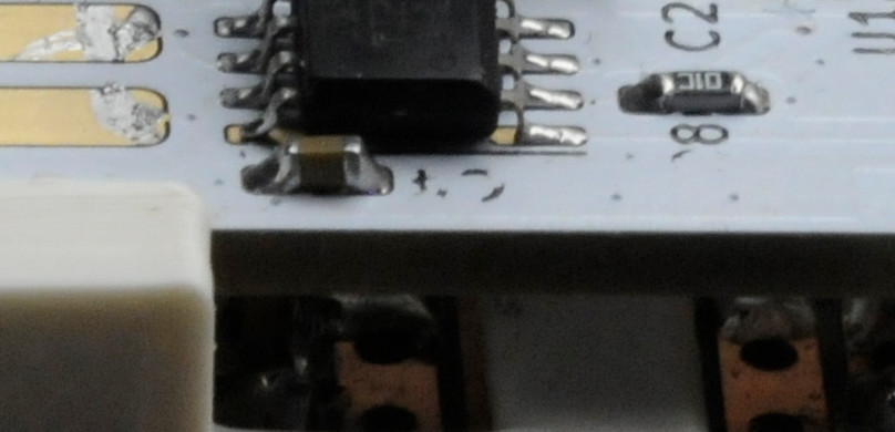 IC lifting its leg.
The wonky test jig caused some headaches, too. Even when a board was aligned properly, the pogo pins would sometimes fail to make contact. This nearly caused me heart failure when I read 9 volts on the 5V supply rail. This turned out to be a ground pin not making contact, impairing the measurement. Luckily, the whole system was floating so no damage was done. But is was scary nonetheless.
One particularly stubborn issue took a lot of time to iron out. In the early phases of testing, the RGB LEDs wouldn’t turn off completely. My first impression was that it would have something to do with the transistors not fully turning off due to some current flowing into the base. Perhaps a tin whisker or some leakage current from the microcontroller (although the latter would be highly unlikely unless the controller was faulty). Finding the same behavior in multiple successive boards rang a bell eventually. It turned out to be a bug in the test code to generate the RGB frames.
Size Matters
It turned out that I didn’t get the dimensions of the board right after all. When the white LEDs are mounted, the assemblies are too tall to fit into the jars. Luckily it’s only by a few millimeters and the problem could be solved by bending the LEDs leads. The bent leads allow the LED housing to move toward the back of the board. One problem with this solution is that the leads come dangerously close to some of the resistors. To prevent any shorts I added some heat shrink as a precaution.
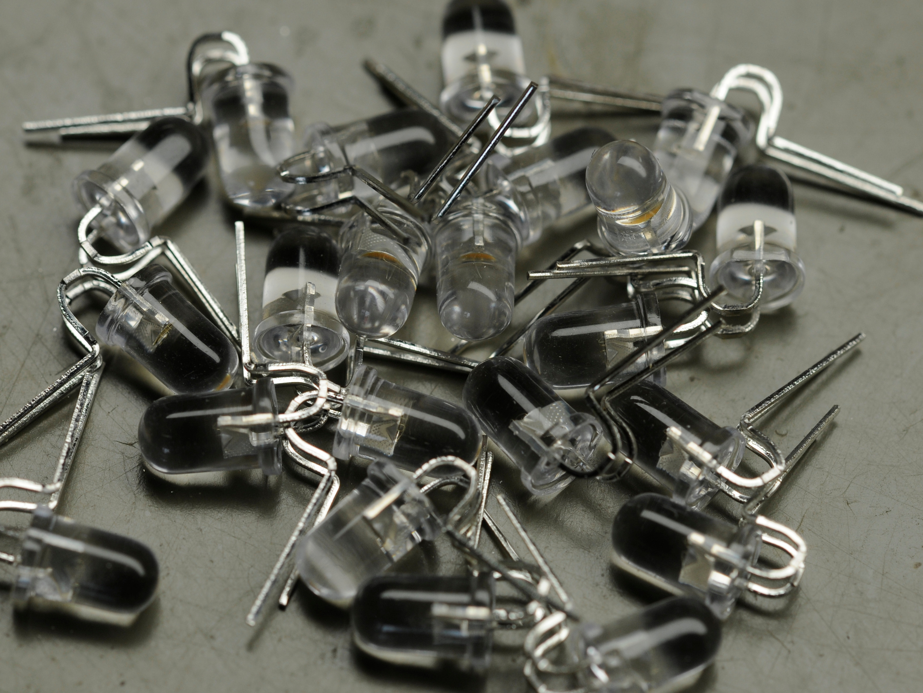 Bent to my will
A Bright Result
It took many hours to solder and test all these boards, but in the end all the LED boards turned out to be in working order. They’re all nicely programmed and the white LEDs have been soldered on.
 Boards at last!
The next post will be about the firmware and communication protocol.