A jar of light
Good news for the visually oriented among you: I will not be boring your pants off this time with a long winded discussion about circuit boards or firmware design. This post in the Party Light series is about the enclosure for the lamps and there will be more pictures! But I couldn’t resist the urge to write a bit about the design, too.
Just as I did in the board design post, I’d like to start with a shout-out to another one of my favorite open source tools: FreeCAD. All my designs for 3D printing are designed with this software. It is the tool that got me hooked on designing my own 3D models (something in which I had no experience whatsoever). Check out their website, try it out and maybe donate if you like it!
Bits and pieces
The lamp enclosures are centered around up-cycled spice jars. The main objectives are strength and ease of assembly. My wanderings into the realm of 3D printing have so far learned me that part orientation matters. The interface between layers are the weak spots while any planar structures can be very rugged. The design will therefore consist of multiple parts that can all be printed separately in their ideal orientation to enhance strength.
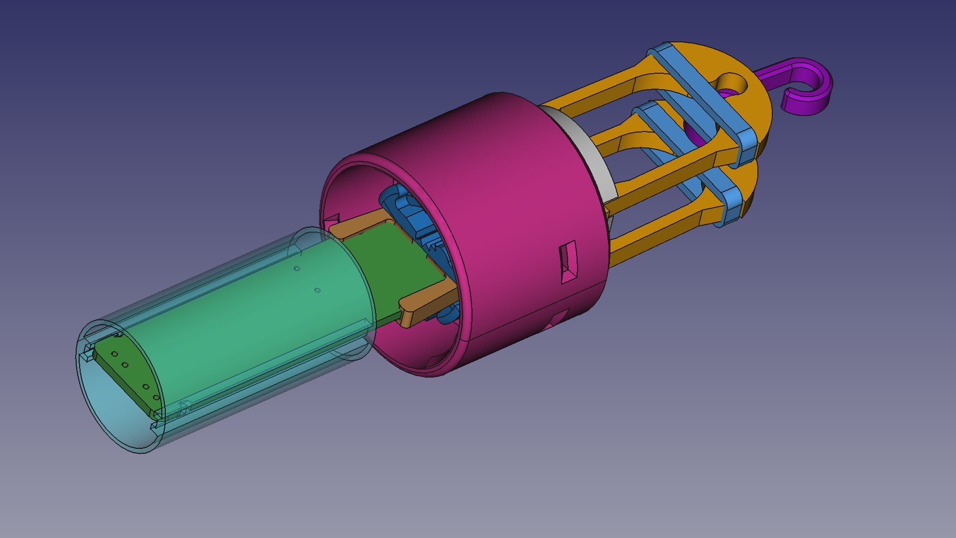 The assembly
The enclosure is made up of three main parts:
- A cap for the spice jar. This attaches to the jar, keeps the LED board in place and acts as a strain relief.
- A rope attachment assembly. This snaps onto the cap and clamps around the rope holding the LED nodes.
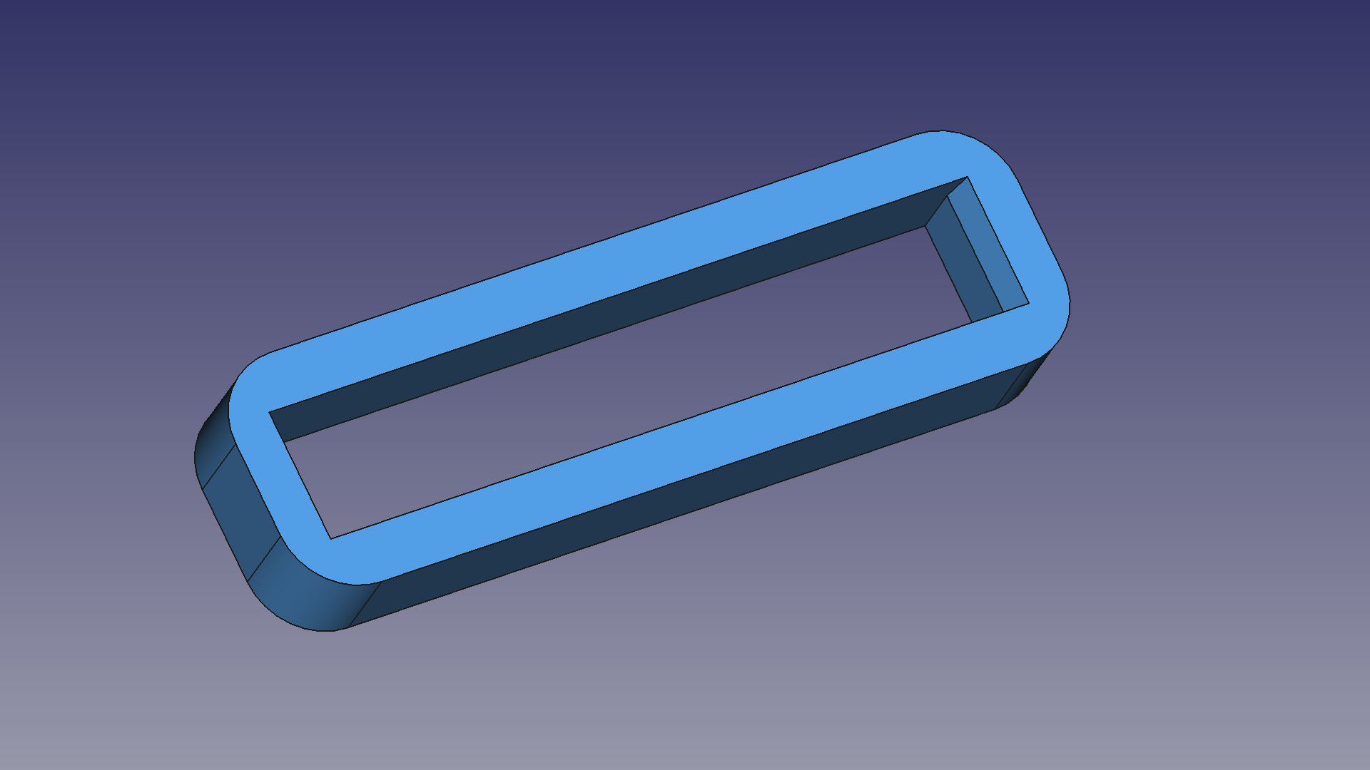
- A diffuser for the RGB LED to enhance color mixing.
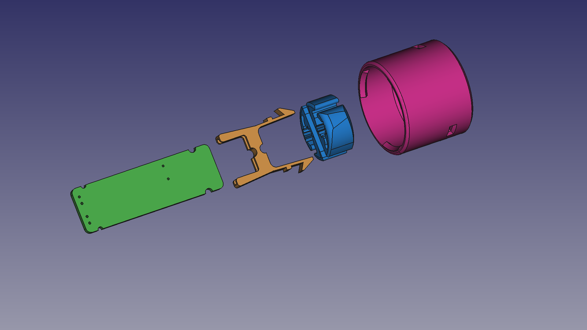
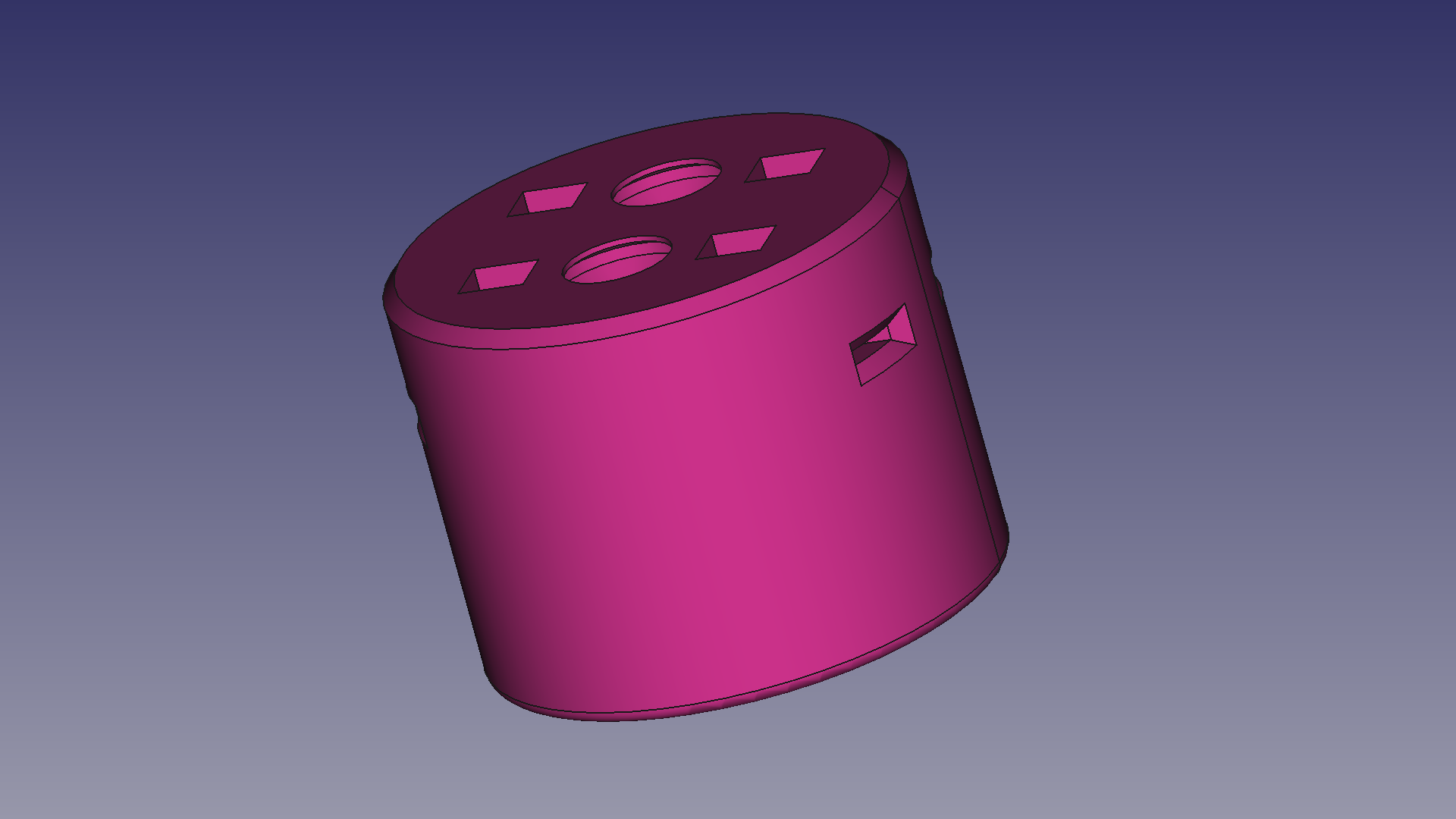
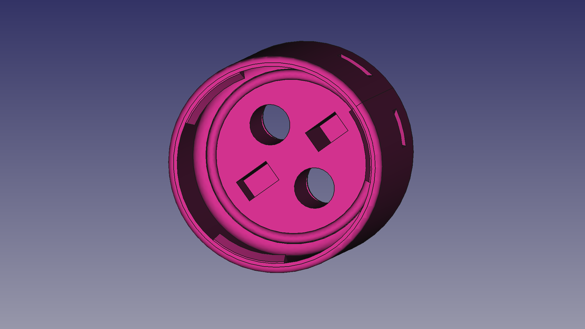
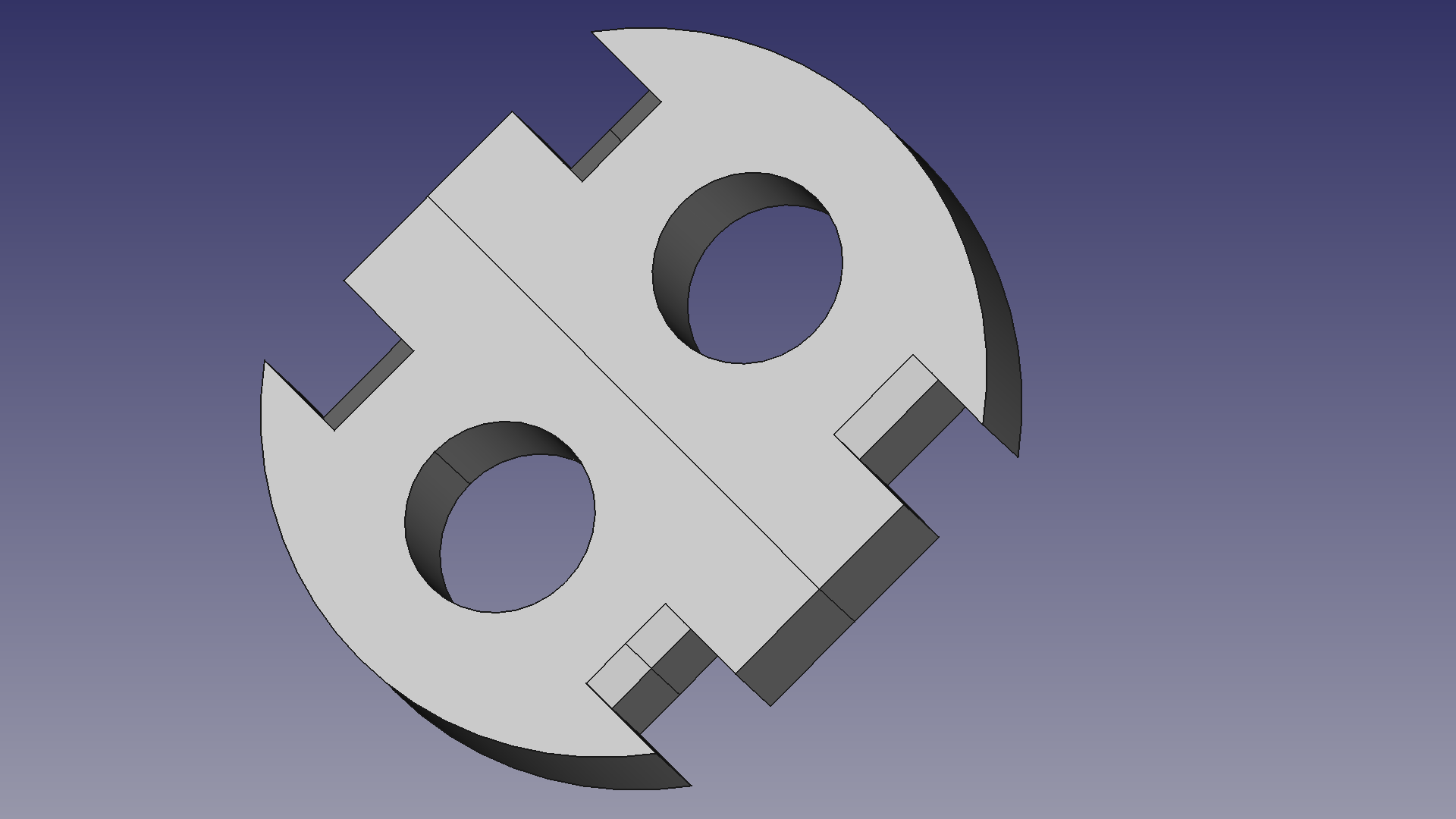
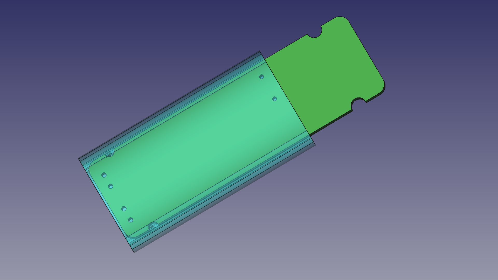
Cap Assembly
 Insert PCB here
The cap assembly consists of, well, the cap. The board mount snaps into that and also holds strain relief in place. The board is placed first, then the strain relief is added and after soldering the cable both the board and the strain relief snap into place. At that point the board is locked into place and won’t fall out anymore.
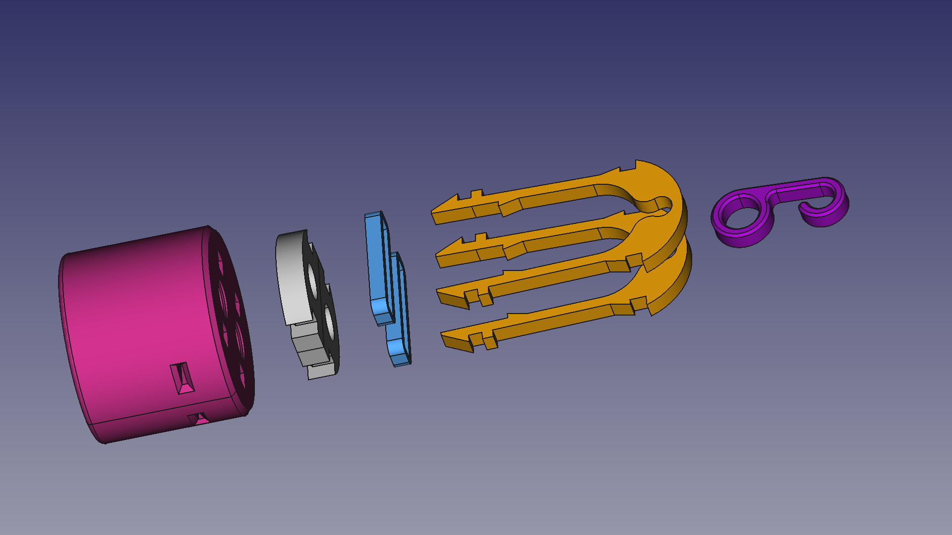
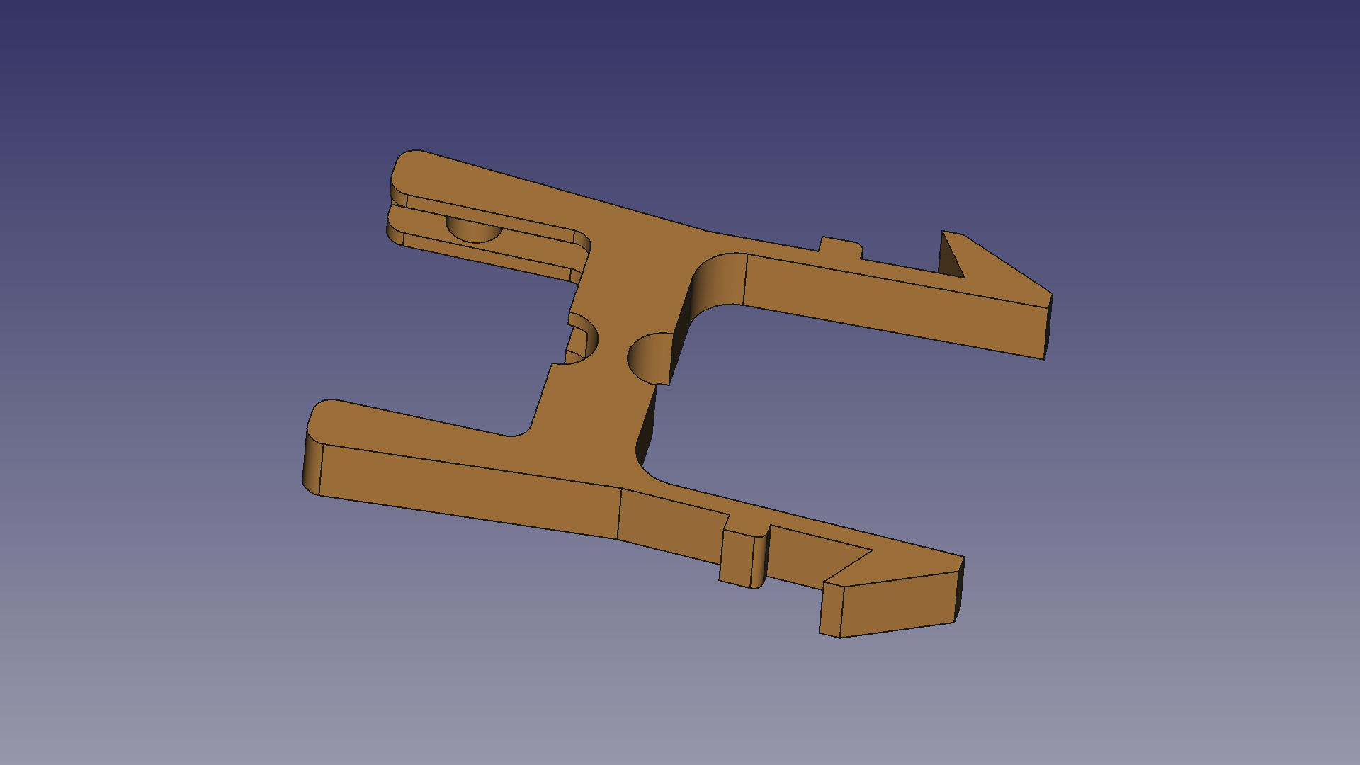
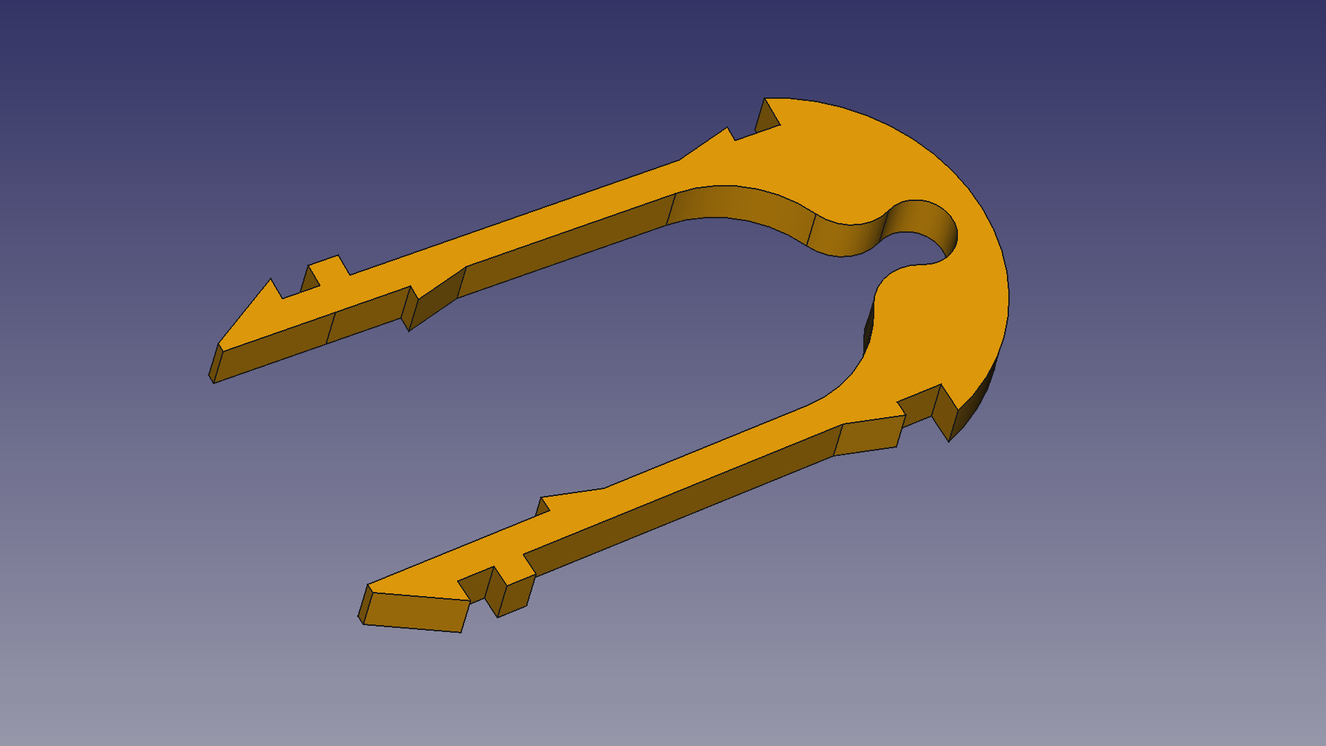
Rope Clip Assembly
 Attach rope here
The upper part of the rope attachment assembly clips onto the rope with a locking bit to keep it firmly attached to the rope. The lower part snaps into a chamber printed into the cap. It wasn’t particularly easy to actually mount it to the rope, but it worked in the end.
Some renders of the individual parts:

Getting a grip
The cables to and from the circuit boards are fed through the strain relief part, which has teeth to grip the cable tightly. Before the part is inserted into the jar the strain reliefs are wide enough to allow the cable to be inserted. The part is slightly conical, allowing it to be compressed gradually when inserted into the mouth of the jar. This then constricts the cable opening, pressing the teeth into the shell of the cable to hold it in place. It took quite some fine tuning to get the dimensions right. Not least because the inner dimensions of the jars have rather wide tolerances. They can be up to a millimeter apart, which causes the effectiveness of the strain relief to be strongly dependent on the individual jars. In the end I found a good middle ground, but ideally the strain reliefs should be printed in dimensions specific for the jar they’re used with.
Oh, Snap!
The enclosures are intended to be assembled quickly and without any additional parts. All parts are supposed to be printed, so no screws. This also saves some expensive threaded inserts or the tedious work of cutting thread into the printed part. The solution of choice to attach the individual parts became snap fits. These turned out to be harder to design than I had anticipated. It took several iterations to get the angle rights, and also the dimensions of the arrow heads of the parts turned out to be tricky. I also found out that (although obvious in hindsight) there is a limit to how small snap fitted parts can be printed. 3D printers can’t actually print sharp 90 degree angles. There is always the inherent fillet caused by the filament flowing out of the nozzle. This is perfectly okay for larger snap-fits where there still remains enough contact area between the cantilever and the chamber it locks into. With smaller parts however, the rounded corners can in some cases prevent proper locking and the cantilever can creep out of the chamber.
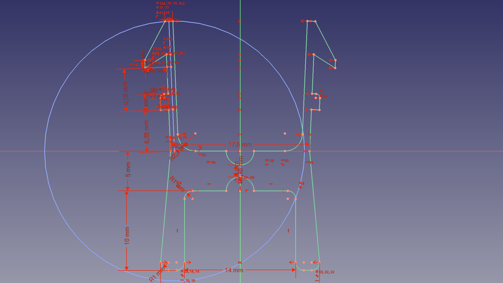 Sketchy
The orientation of the print, as mentioned above, also matters. In my experiences the only way to print the cantilevers reliably was to print them laying flat on the print bed. When printed vertically the parts would inevitable break in two. I must admit though that I’ve had layer adhesion issues before with the filament I use. So it may the slicer settings or even the filament itself.
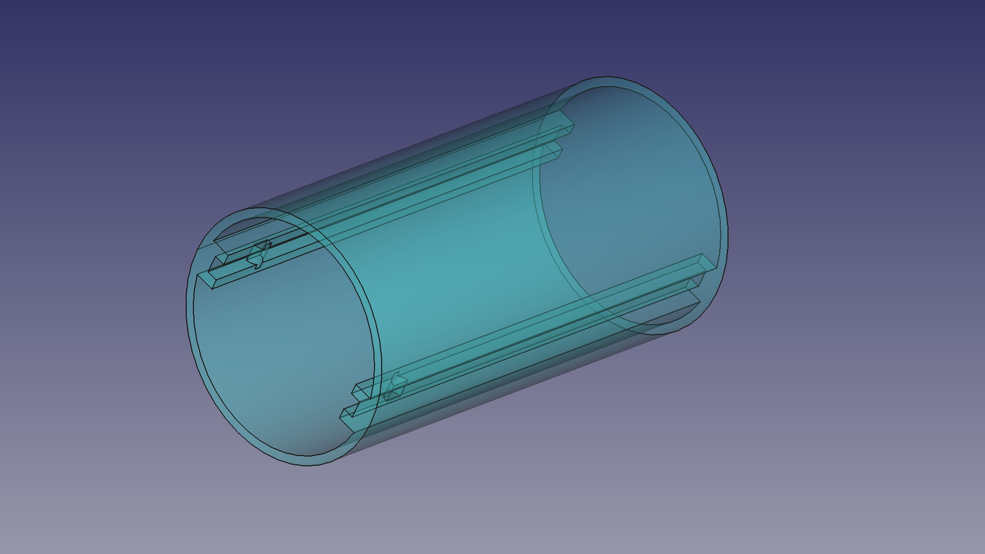
A Trick Of The Light!
The RGB LEDs for the mood lights are bright point sources of light. They’re not very pleasant to stare directly into, and as it’s not the intention to burn the light effects onto the viewers retinea, some form of diffuser is needed. I ordered spool of transparent PLA to print the diffusers from and was surprised by the ease with which the desired effect was achieved. I initially expected that I’d have to print some sort of texture into the part to get the desired effect. It turned out however that the layered nature of the prints made a very nice diffusion effect on its own!
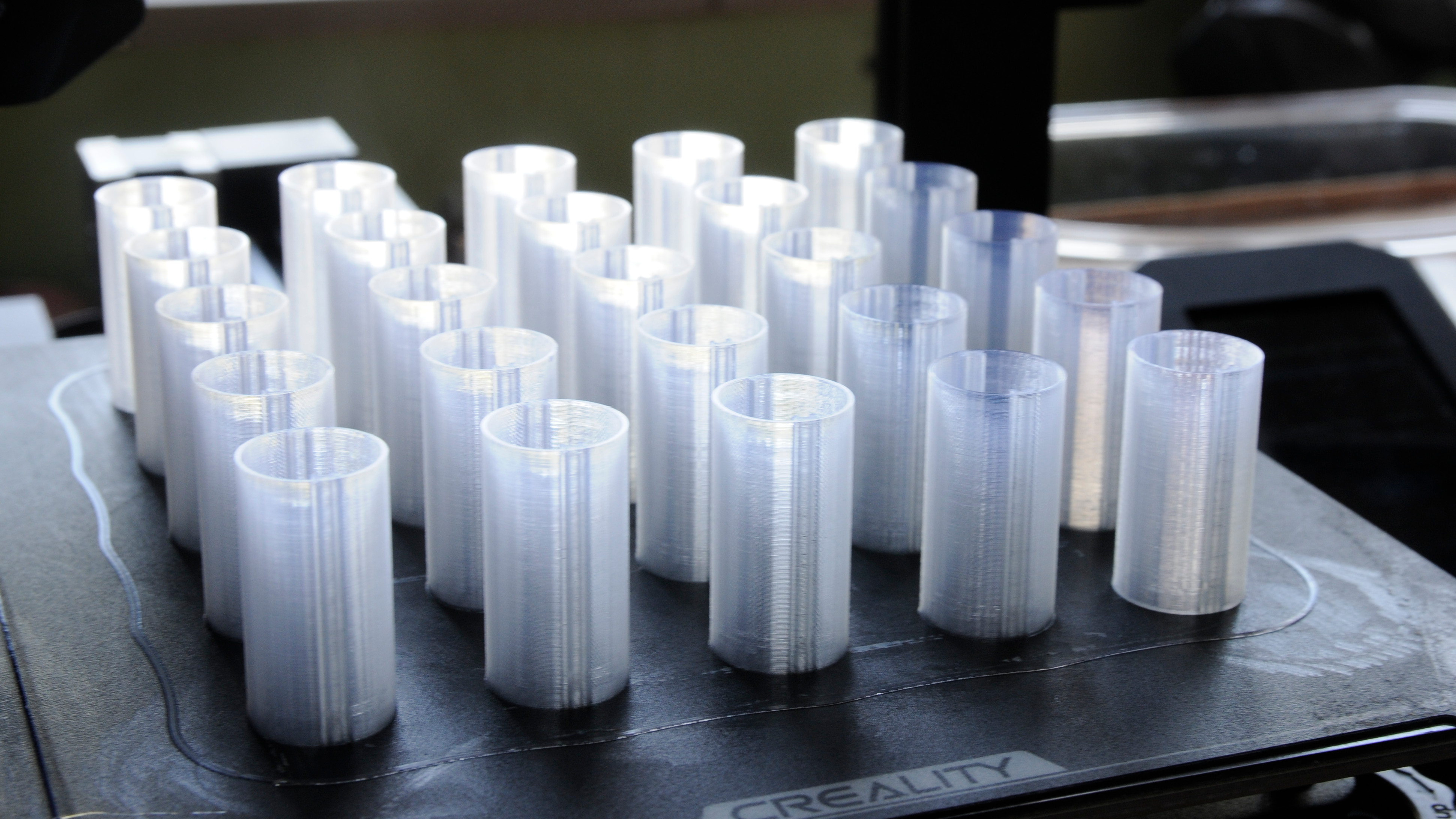 Freshly printed diffusers
The diffusers slide over the LED boards and have a notch inside that lock them to the boards. The material is a bit springy, allowing the diffusers to be bent slightly when they’re being installed.
Staying Dry
The party lights are meant to be used in a tent. Tents happen to live outside a lot, so some precautions had to be put in place to protect the electronics from the elements. I considered gluing the cap assemblies to the jars, or even potting them with hot glue but that didn’t seem like the best solution. Sealing the jars hermetically will trap some moisture into them, which will eventually condensate when the weather gets colder. Temperature differences will also cause some pressure to build up inside the jars. On the other hand, some water-tightness is still desired. I ended up with leaving some free space between the jar and the cap, so trapped air can get out. This will hopefully address the problems with condensation and air pressure. To prevent small water droplets (or minor rain) from entering I added rubber seals at the cable entries.
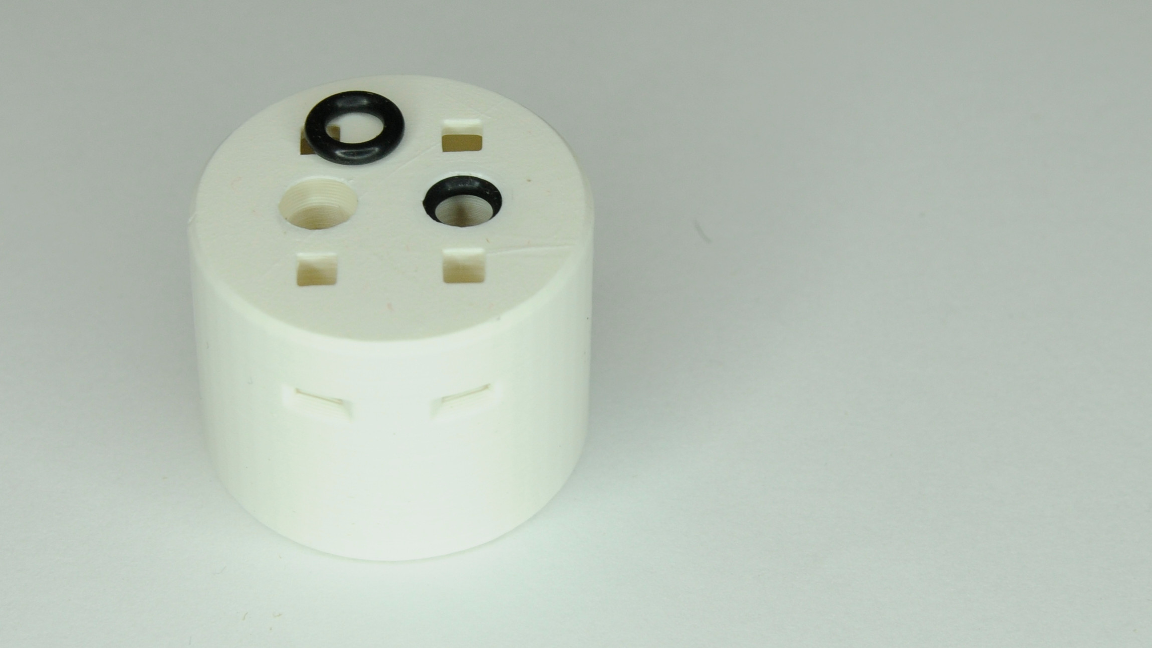 Rubber prevents unpleasant surprises
By the way, if you wonder why there are extra holes at the side, that’s also to get rid of water. In case any seeps in via the pockets for the rope attachment clips.
Stringing It Together
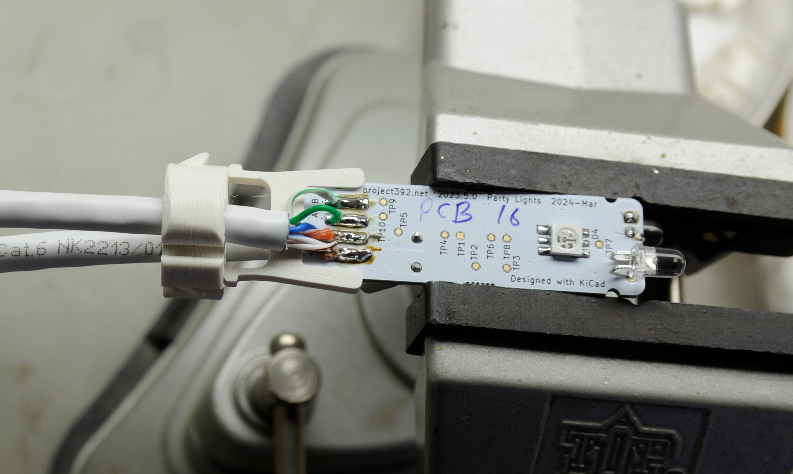
I haven’t yet mentioned how the wires are connected to the boards. They’re soldered. One of the twisted pairs in the UTP cable is soldered to the data inputs, while the others are in parallel to provide power. This meant a lot more soldering. Not to mention stripping all the wires and feeding them neatly into the enclosures.
 Solder on…
As an extra precaution the conductors are held in place with some (or, rather a lot) hot glue. This not only aids the strain relief, but also keeps the conductors from bending during assembly.
Please note that the cable is flexible (multi strand) UTP. The rigid type would be much too sensitive to breaking when bent.
Hang on!
If you were to buy a set of party lights, you’d notice the absence of a piece of rope holding all the lamps together. In a production unit, all the lamps (or their sockets) are overmolded onto the cable. This allows for the force of gravity on the lamps to be transferred to the cable without causing to much strain on the conductors.
With the do it yourself approach in this project there’s not the luxury of overmolding the cable. Also, the strain relief isn’t strong enough to hold everything in place if gravity starts pulling on a bunch of glass jars. With glass being several millimeters thick, the weight is significant. Without a means to remove the strain from the cable, the conductors will be pulled clean off the boards.
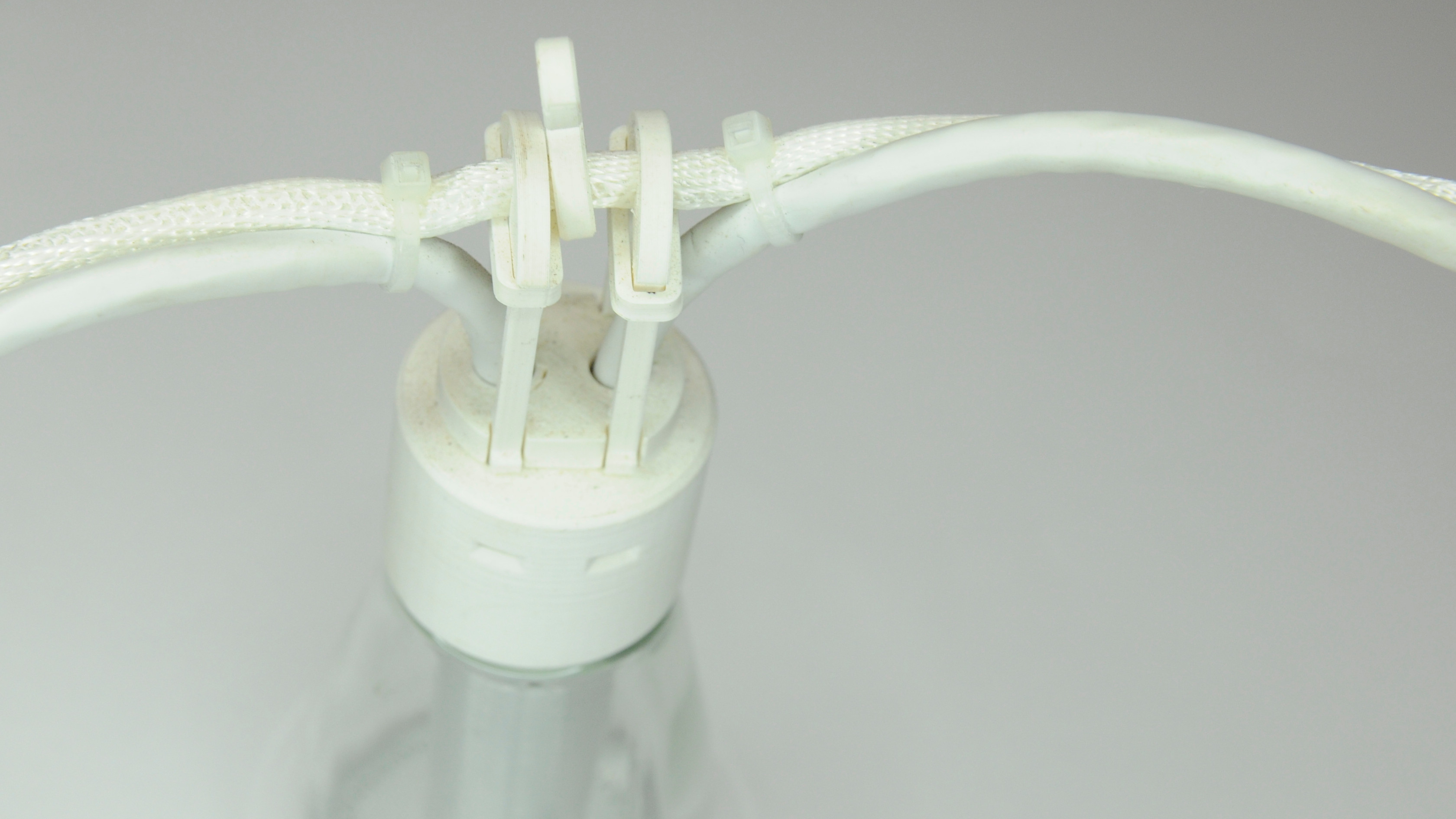 Hooked
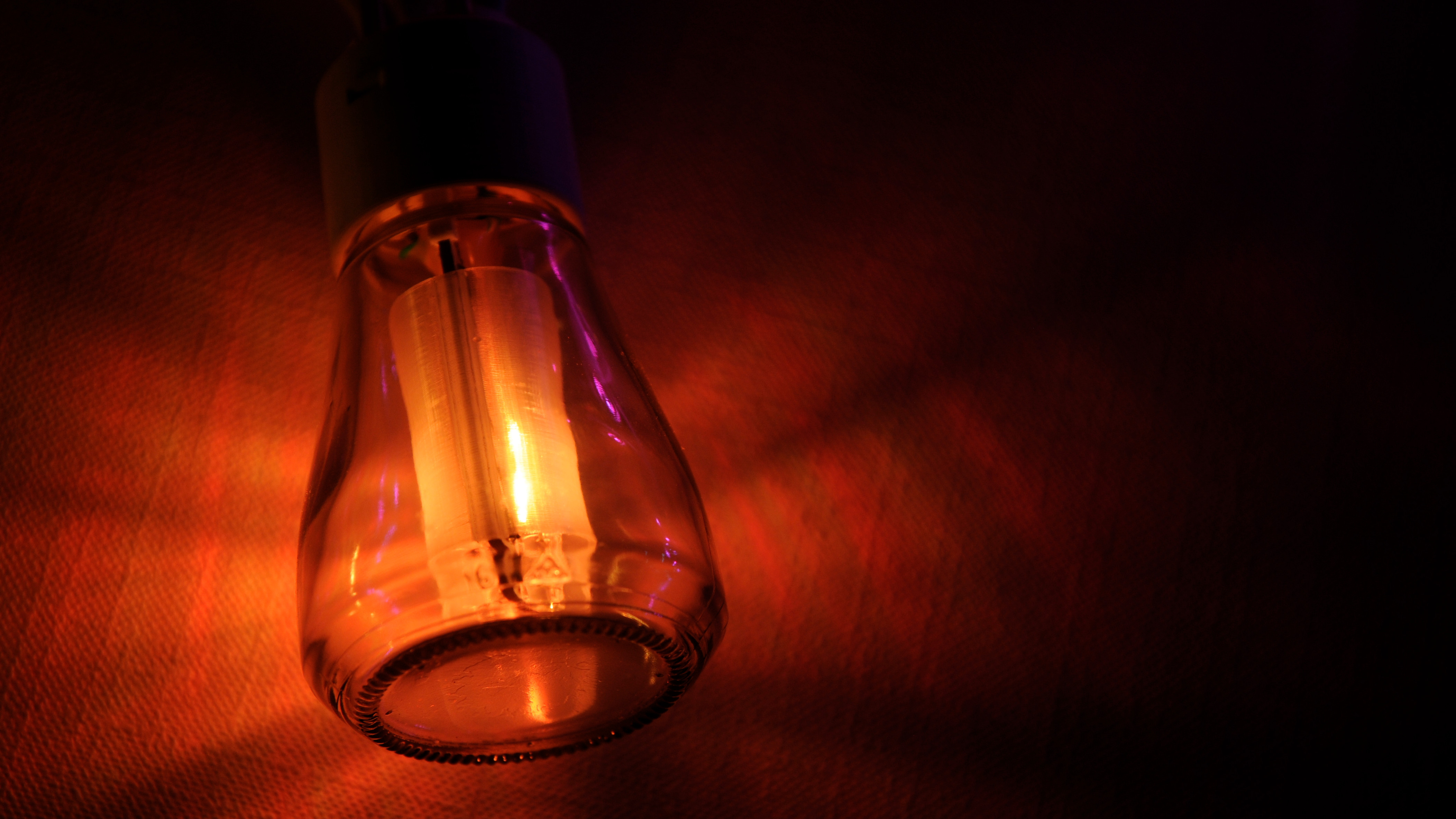
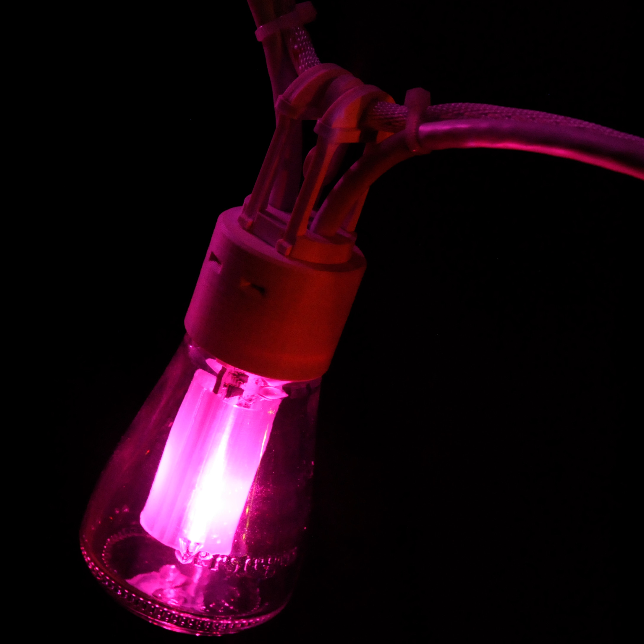
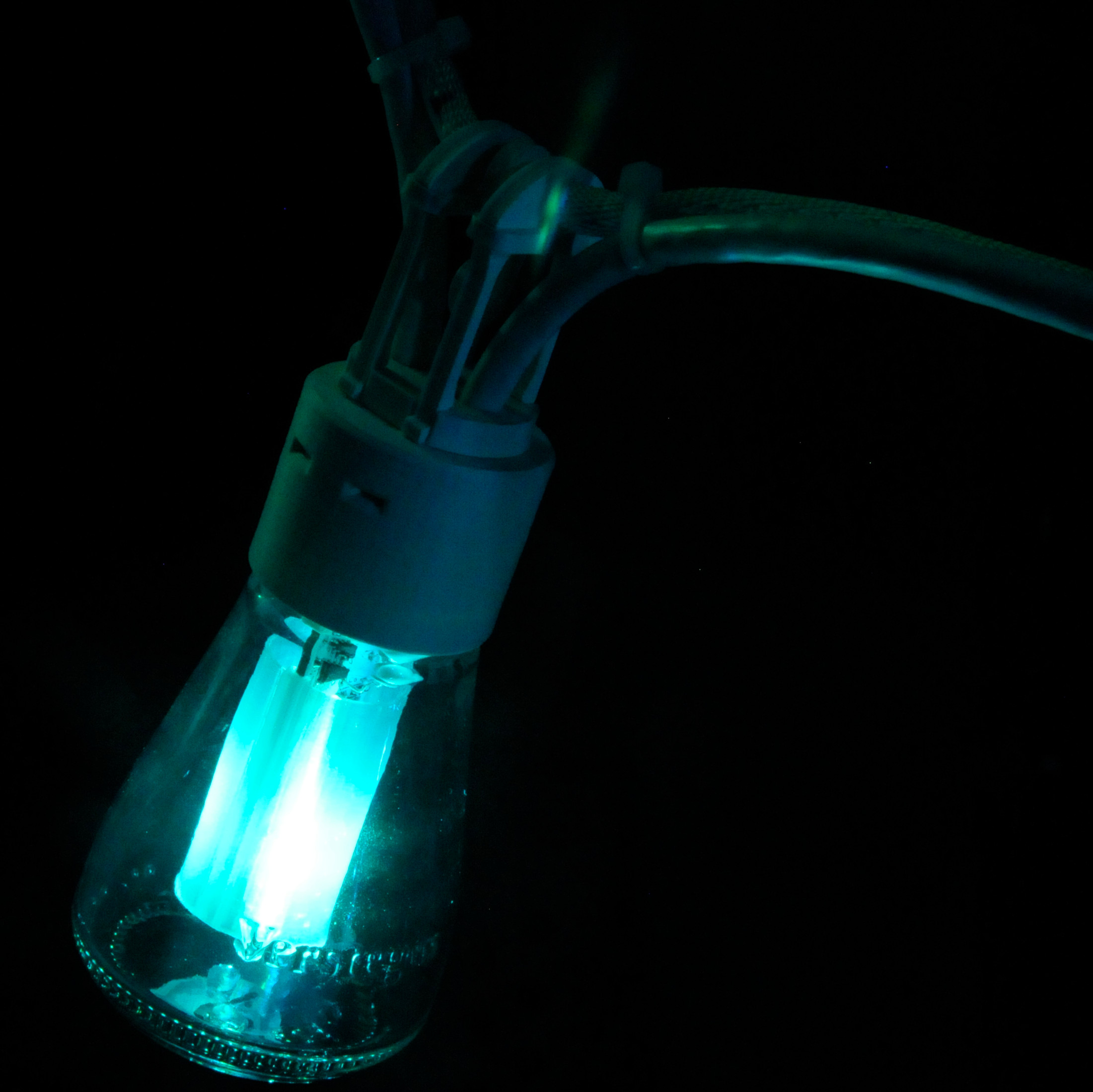
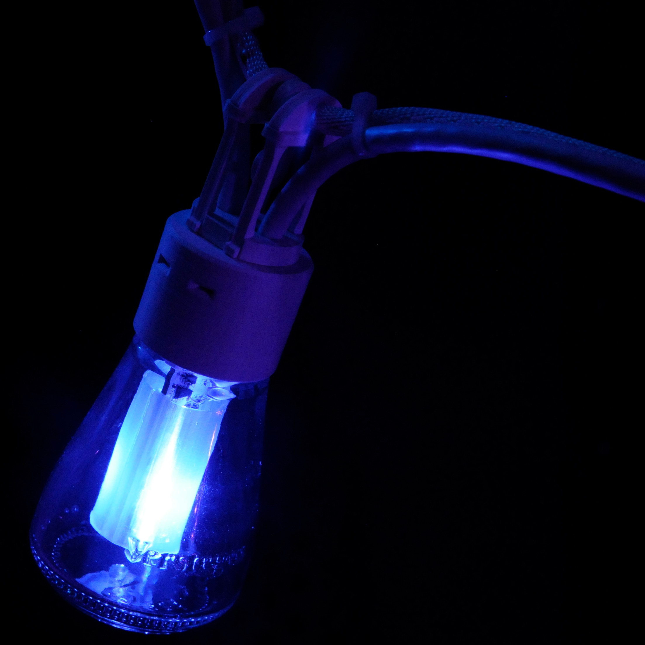
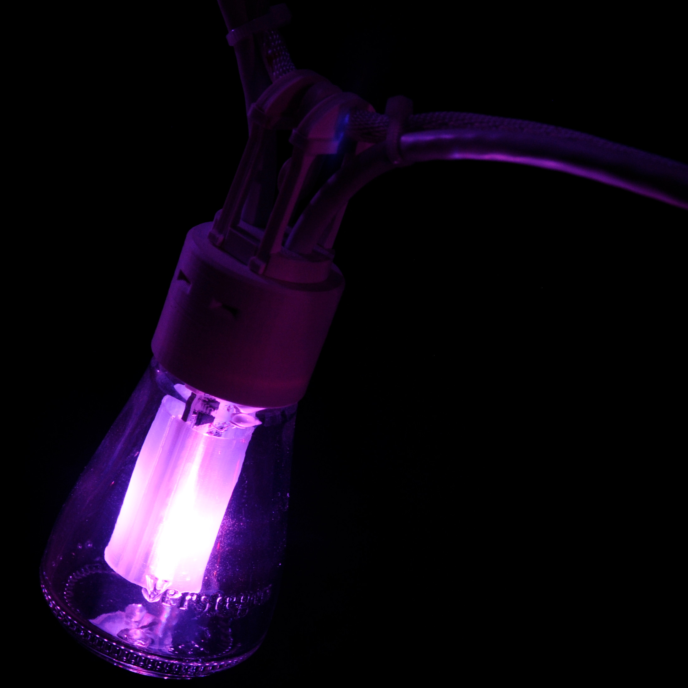
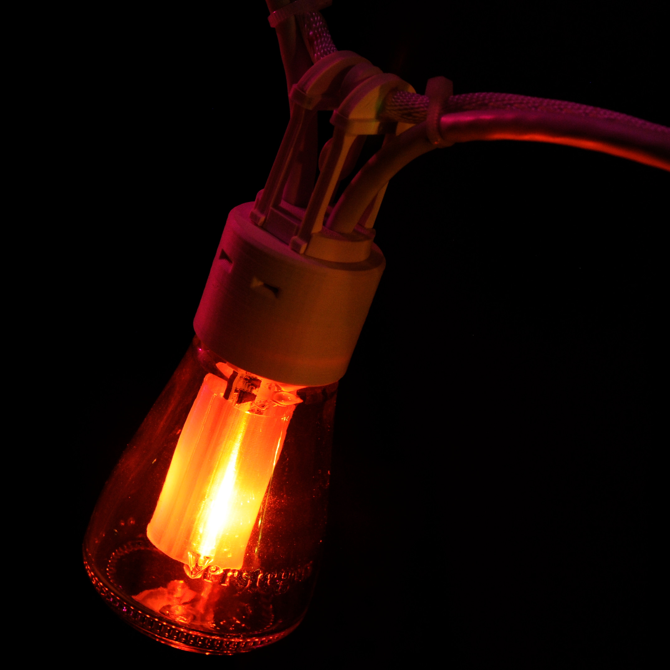
Shine On
And here’s yet another picture of result, with the LED shining and all!
Like the rest of the project, the design for the lamp enclosure can be downloaded from my Gitlab repository.
With the lamps up and running we can move on to the controller board, which will be covered next.