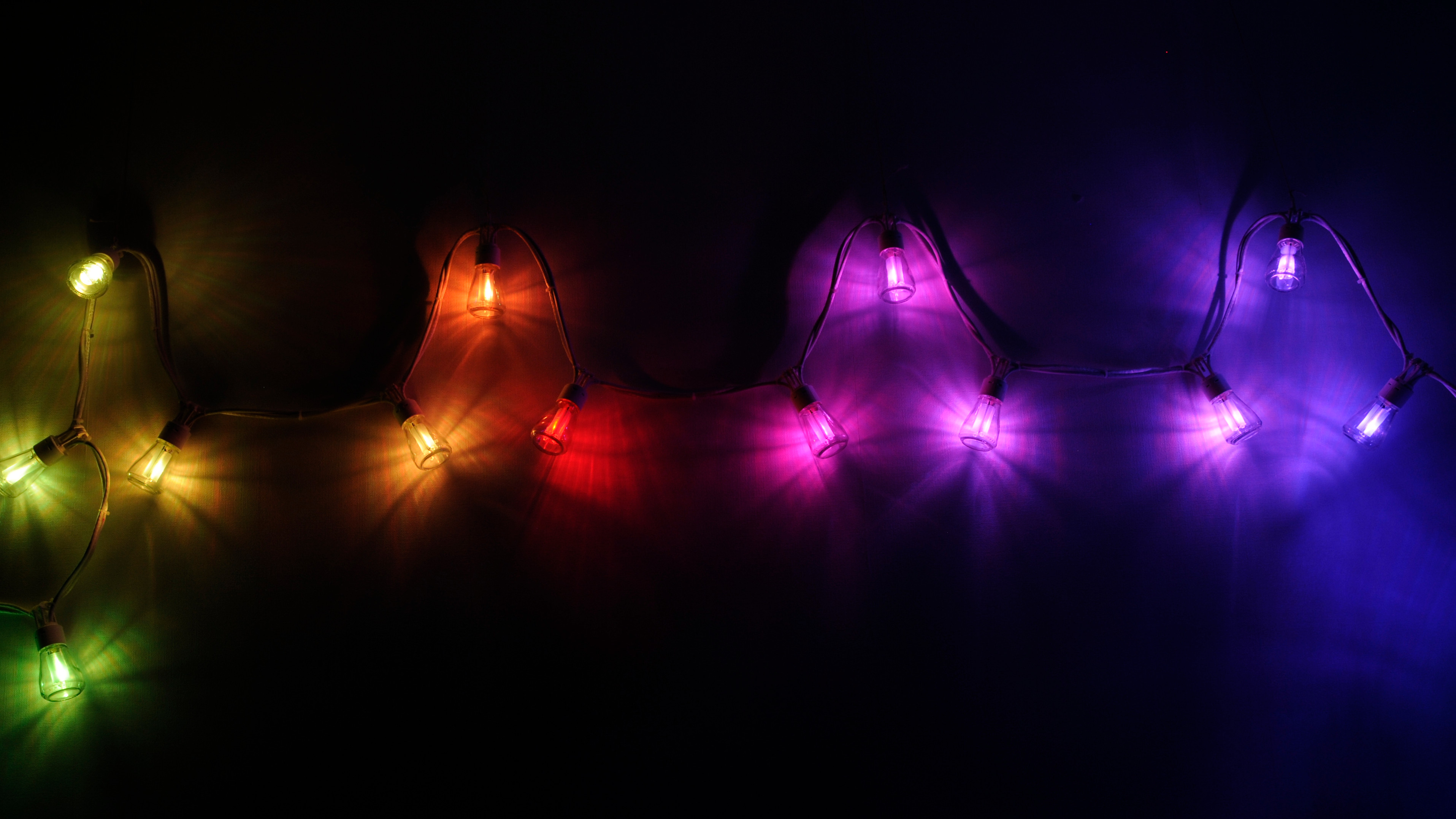
And there were lights!
In this article I’ll discuss how to project went and what improvements could be made for future iterations.
Retrospective
How did it go? To be totally frank, I’m actually very happy with this project! There have not been any show-stoppers and I ended up with a working product before (albeit close to) my deadline.
The only noteworthy design issue that had to be addressed was a mistake in the calculation of the output capacitors for the switching power supplies. Luckily I was able to fix it. Not in a pretty way, but fixed it all the same. I corrected this mistake in the design files as well.
I’ll now go over some potential improvements for future versions of the design. Starting with the electronics.
Electronics Improvements
LED boards
My major annoyance with these boards is that I can’t put the microcontroller in sleep mode without the LEDs turning on. This can simply be addressed by adding pull-down resistors at the MCU outputs. So that’s one improvement to start with.
Putting the microcontroller in proper sleep mode would be utterly pointless if the voltage regulator keeps drawing a quiescent current that’s an order of magnitude higher than the MCU stand-by current. So next on my list is a more efficient linear voltage regulator. The Diodes AP7375 1 looks like a good candidate for the job.
Here’s an even wilder plan regarding the power supply! If the budget allows it, it could also be considered to replace the linear regulator by a switching regulator. This would add significantly to the part count and complexity and may not even fit on the tiny LED-board. But if it would be done, the supply voltage could be raised, lowering the current end thereby the resistive losses in the cable. This would in turn allow for a longer cable or more nodes. The LEDs would in this scenario have to be powered from voltage regulator instead of directly from the supply cable. This would further improve battery life as it would eliminate the series resistance that’s needed in the current design. The series resistors for the LEDs could potentially be left out completely, provided that the supply voltage is below the break down voltage of the LEDs. Extreme care would have to be taken however to prevent the firmware from ever putting a 100% duty cycle on an output.
One last suggestion regarding the components would be to use a microcontroller with more flash memory. This would allow for added features, such as the factory mode I had in mind. It would also allow for higher resolution dimming of the white LEDs via the UART. The current firmware can only do a limited number of steps because I ran out of flash. The alternative microcontroller may not have the low pin count that the Attiny402 has. Nor the pleasant price tag. On the plus side, it may come with more timer/counters and PWM outputs, so we don’t have to resign to the UART hack to dim the white LEDs at all.
The LED boards are slightly too tall for the enclosure. If the components are crammed together more closely there might be some slack in the board dimensions to make it fit. An alternative solution would be to adjust the enclosure design for a larger container or to 3D-print a transparent enclosure instead.
Controller board
The problem with the SMPS output capacitors has already been corrected in the design. The LDO, which has a high quiescent current, has not yet been replaced by a more efficient part. A suitable replacement would be the Richtek RT9058-332 which only draws a 5uA quiescent current.
There are more elegant solutions for reverse polarity protection than the (rather crude) method employed in this design. I would suggest adding a P-channel MOSFET with its body diode forward biased and a negative gate-source voltage with a resistive divider. This is a common technique for efficient reverse polarity protection: when the voltage is reversed, the diode blocks the input current. When forward biased the diode will conduct, providing a gate-source voltage to the gate which turns on the MOSFET. The MOSFET then bypasses the diode and eliminate excessive losses caused by the diode voltage drop.
The footprints for the microcontroller and the switch mode converter have excessively large pads. These can be reduced to their normal size (or perhaps slightly larger than that).
For this design I opted for the STM32F0 series microcontroller. ST also offer an STM32G0 series that is targeting cost effective applications and also runs at a higher clock frequency, In hindsight this may have been the better option for the controller board from a cost perspective, but not when it comes to performance.
The controller firmware is still in the making at this point. The microcontroller has 32kb of flash, which might be a limiting factor for the light effects and configuration options that the controller is capable of. A microcontroller with more flash memory might be necessary. The same goes for the processing power of the Cortex M0 chip. It is likely to be sufficient to generate light effects at an acceptable frame rate, but it might run out of juice if it has to do audio processing as well. An STM32F3 series microcontroller might be a better fit, both for flash and processing power. The F0 and F3 are largely compatible but they are not drop-in replacements of one another. For one thing, the power supply scheme and decoupling capacitors differ.
Board Manufacturing
I said it before: soldering 25 boards (albeit tiny boards) is tedious work! Having the boards panelized helped with doing the job efficiently but its still a lot of work. For future projects it might be worth considering having the boards assembled by a fabricator if the price is acceptable. It would already help a lot if all the passive components were assembled. The ICs can be hand soldered. A low cost reflow oven may also be an investment to consider.
Enclosure
Lamp enclosure
The lamp enclosures turned out to be a lot more work to design then I had expected. I probably made the design overly complicated, but as I’m not a mechanical engineer I can forgive myself for that. In fact, I’m very happy with the result! Especially given the fact that I never designed anything this complicated in 3D CAD before. It was an interesting journey into 3D-design and I learned a lot.
Controller
The controller enclosure is also a design that I’m happy with on the whole. The strain relief needs some fine tuning to make it work. The snap-fit mechanism to mount the circuit board and to lock the two halves of the case together work good enough. If you don’t intent to open them too often at least. And lets face it, when the firmware is finally ready the case doesn’t need to be opened anymore.
The 3D-printed light pipes didn’t have the grand effect I had hoped for. Maybe light pipes can’t be 3D-printed. If someone knows how it’s supposed to be done, please let me know. In future I would probably go for off-the-shelf light pipes. They’re more expensive but easier to use.
Next Revision…
Will I make a new version of the designs to incorporate the proposed changes? Probably not. I’ve been working on this for several months and I’m way overdue for the next project. So, any improvements to this design are left as an exercise to the reader. You can clone the project from its repository and start tinkering with it yourself.
And Firmware?
Although I have a working product with the demo firmware, I do seriously consider continuing the development. The controller does not even remotely do what I pictured it to do. So if there is to come a follow-up post, it would be that.
Go Tinker!
Let’s conclude (for now) with an invitation to adopt this project for yourself. Clone the project from my repository and get started! If you do, please respect the license. All my hardware projects are published under the reciprocal version of the CERN Open Hardware License. This basically means you are free to use and, modify the design as long as you publish the modified design in turn. This way my project and any forks that may come from it will remain open and available to anyone. All code is released under the GPL3 license.
All design files are on my Gitlab repository. When there are updates I will add new release branch.
Ps. There’s also a Project glossary that includes extra pictures!