Zipping up the zapper
In the previous article of the party light series I discussed the build and testing of the controller board. This following (shorter) article will cover the design of its enclosure. This, like the lamp enclosures, was designed in FreeCAD. It is meant to be 3D-printed.
Boom!!
Lets have a look at an exploded view of the assembly.
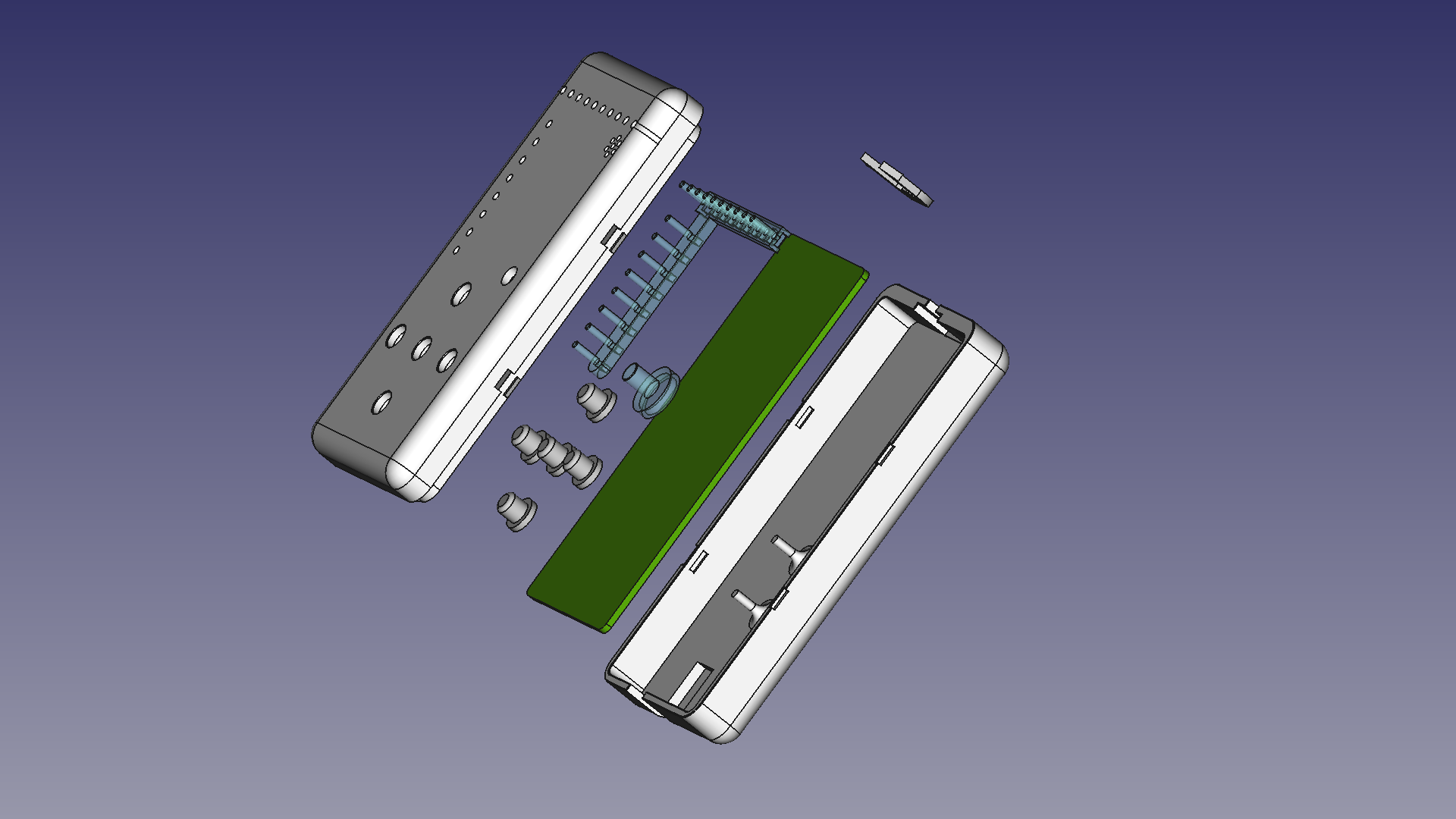
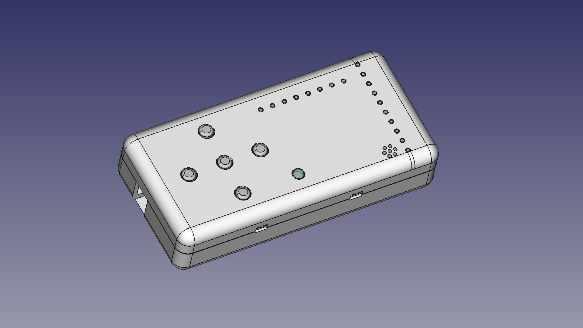
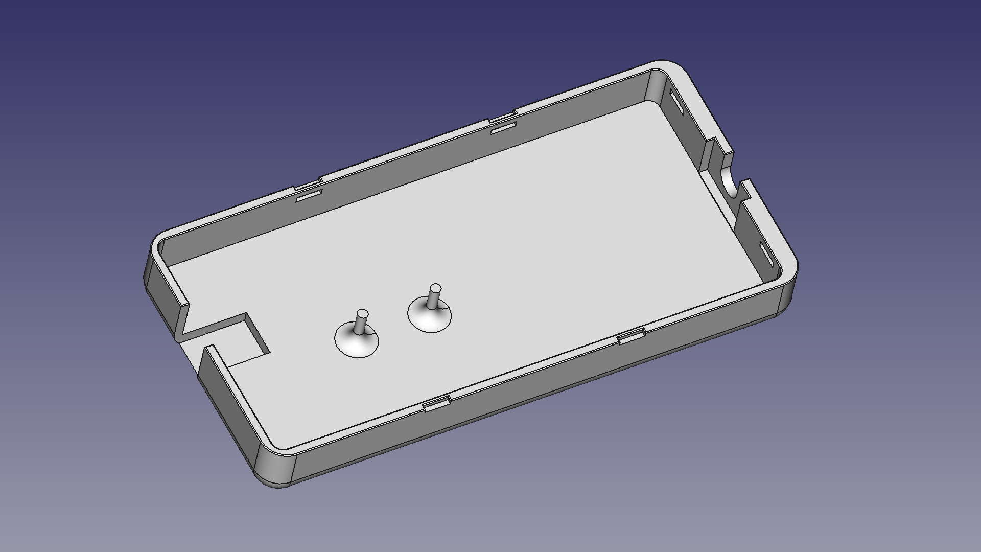
The case consists of two halves. The top face has holes to accomodate the buttons, light guides and microphone. The caps for the buttons and the light guides are 3D-printed as well.
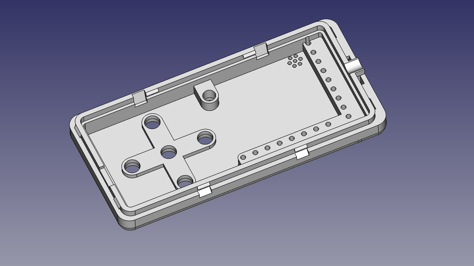
Both the top and bottom part have openings for the power inlet to poke through. The inner rim of the top part supports the PCB. The bottom halve has two rods that provide extra support below the push buttons. This is to prevent bending the board as the surface mount parts won’t like that very much.
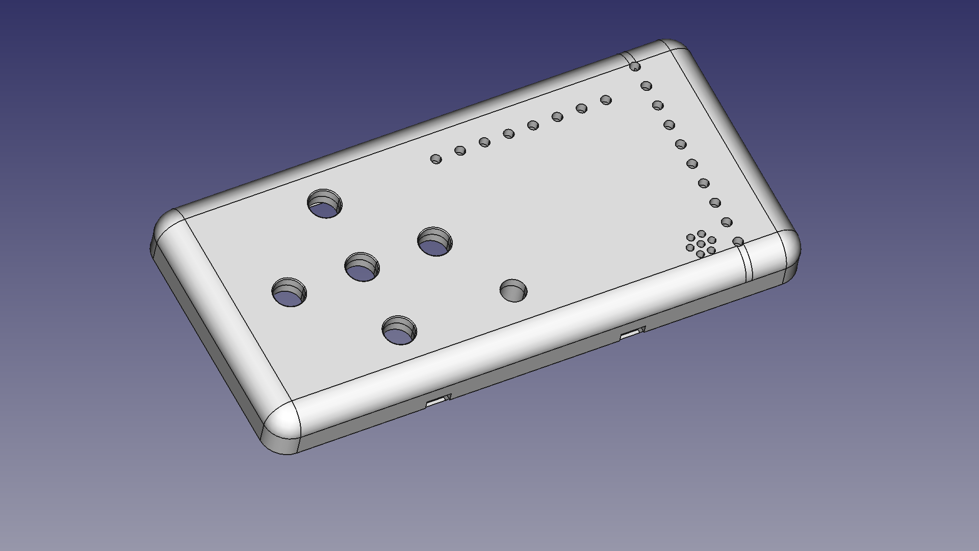
More renders of the parts:
And Then It Clicked!
Both the PCB and the two halves of the enclosure lock in pace with notches printed at the sides of the parts. The material is sufficiently elastic to allow the box to be opened again if need be. I did find however that the enclosure gets damaged easilly when it is prised open again so it can’t be reopened indefinitely.
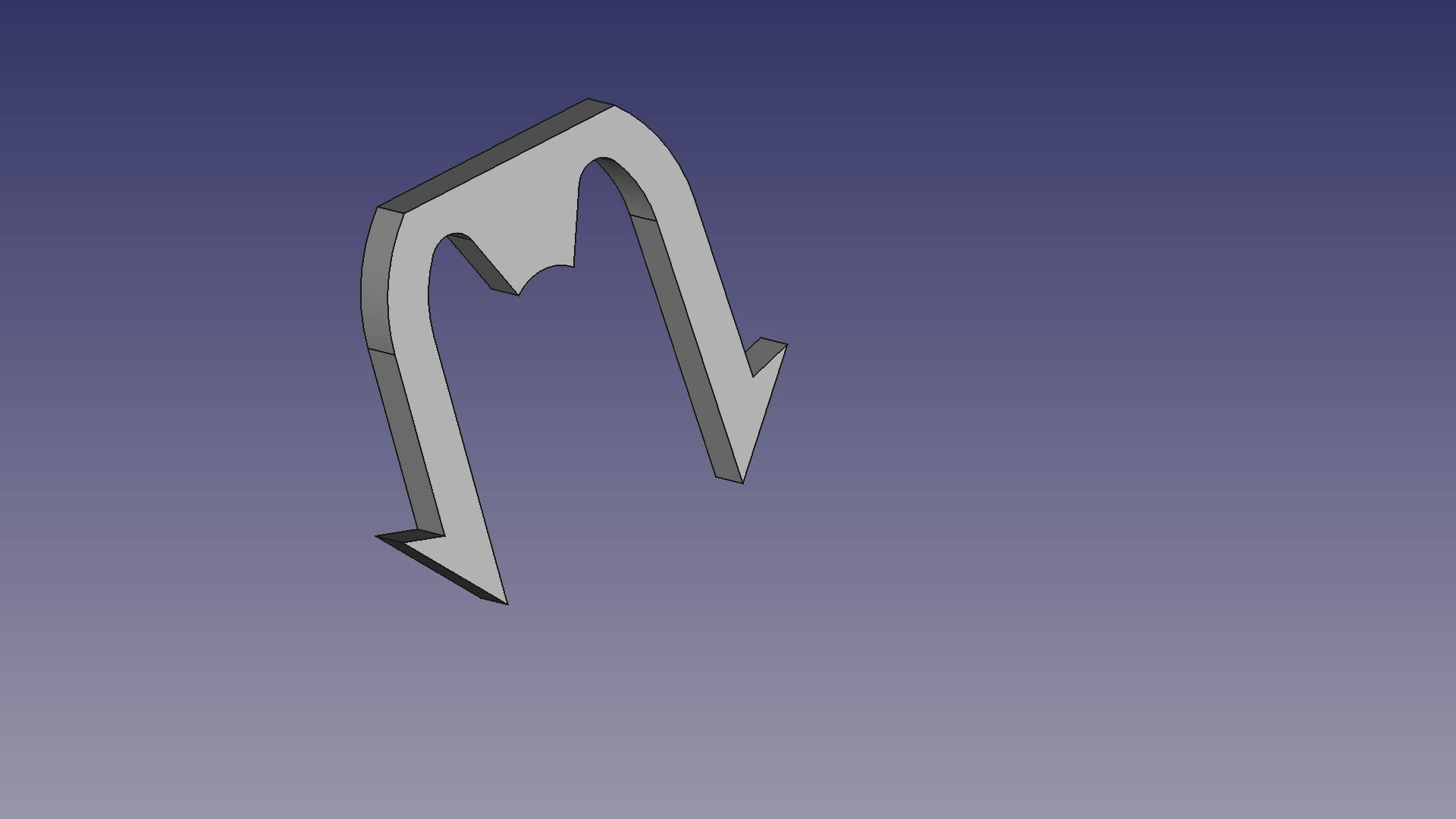
The strain relief was designed in the fashion of the retaining clip from the lamp enclosure design, but it didn’t realy work out for this part. The part isn’t strong enough to hold the cable in place, so in the end it had to be gued in place instead.
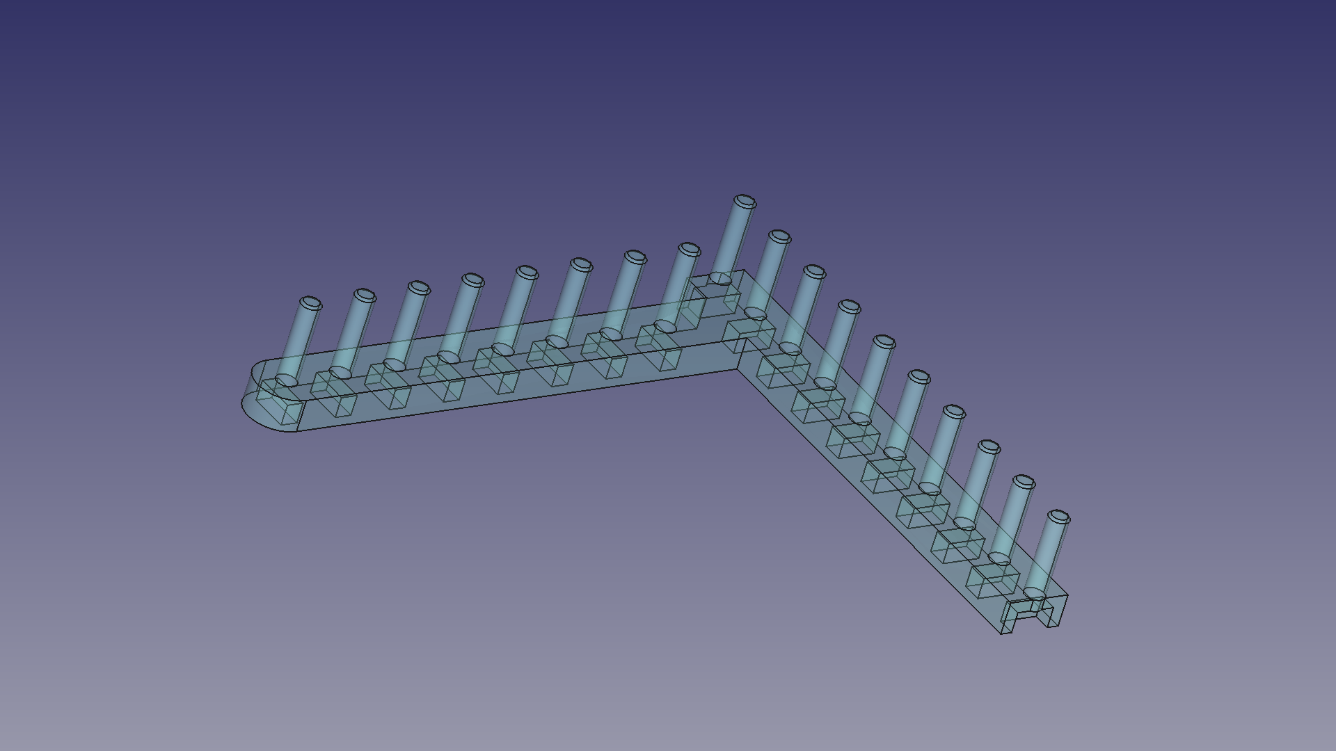
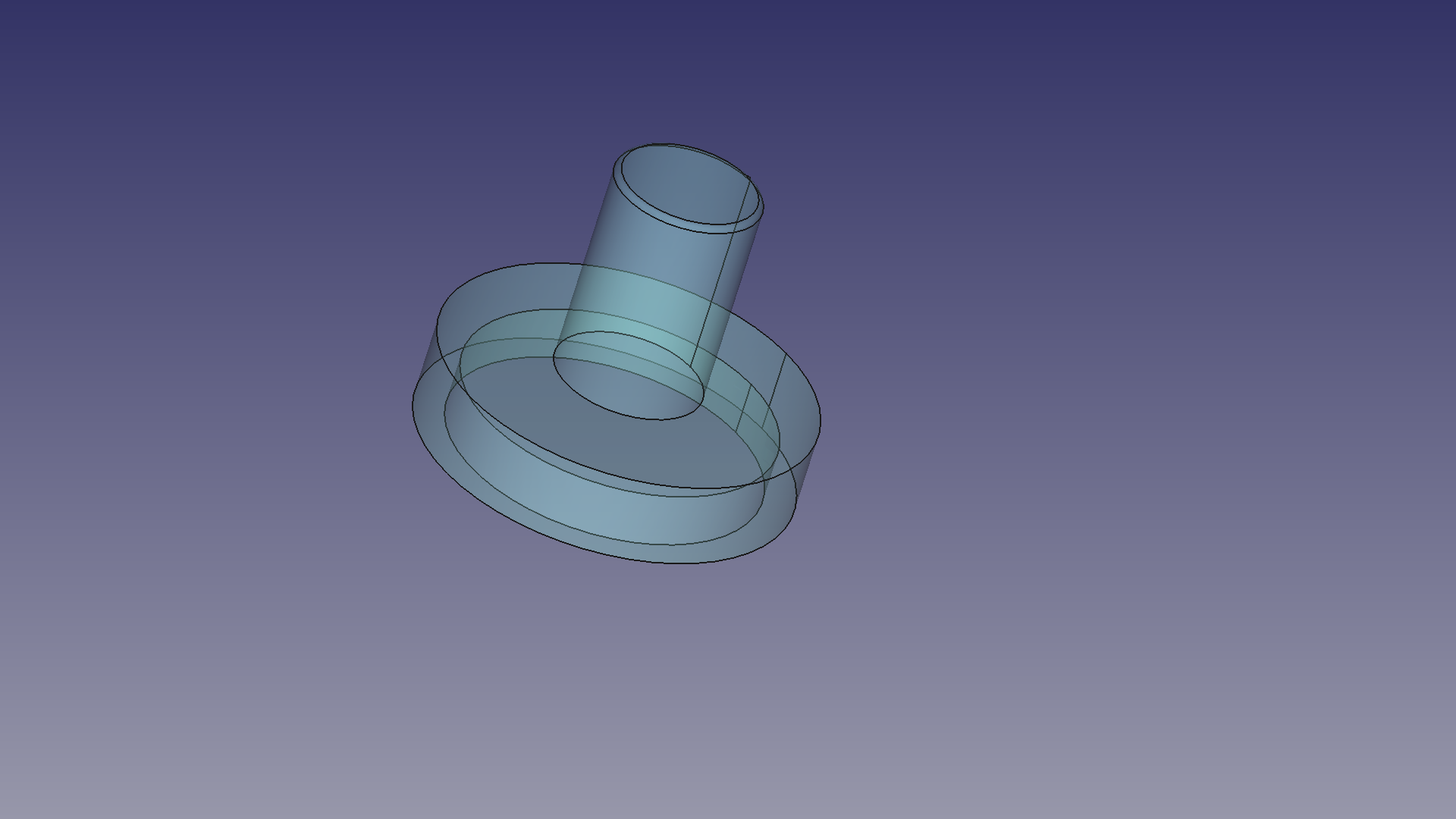
Guiding The Lights
The Light guides are placed over the LEDs and are supposed to guide the light nicely through the holes in the enclosure. The only problem is that… they don’t. They let the light trough alright but don’t really act as light guides in the usual sense. The LED just shines right trough all of the transparent material and also trough the top cover. Normally with a ligh guide it looks as if the LED is embedded into the front cover. In this case however I got a fuzzy spot surrounding the hole in the cover. I ended up inking the parts of the light guide that arent’t supposed let light through with a black sharpy. That did the trick but it’s still not a satisfying solution.
Smoothing It Out
The enclosure is supposed to have a rounded, smooth surface, but 3D-printers don’t usually make that. So the printed box had to be post-processed to some extend. I sanded it with a rough, 120 grit, sand paper and then polished it with 400 grit water proof sand paper for a smooth surface. I installed the transparent parts for the LEDs before the final sanding to give the LEDs a diffused look. The material hasn’t been coated (due to lack of time to research 3D-print coating). If you opt for sanding your prints too, please do keep in mind that adequate breading protection is highly advisable!
To prove that I realy did print the enclosure, I’ll conclude this post with a picture of the thing. Covered in grime and all, so you know it’s also been used in the wild!
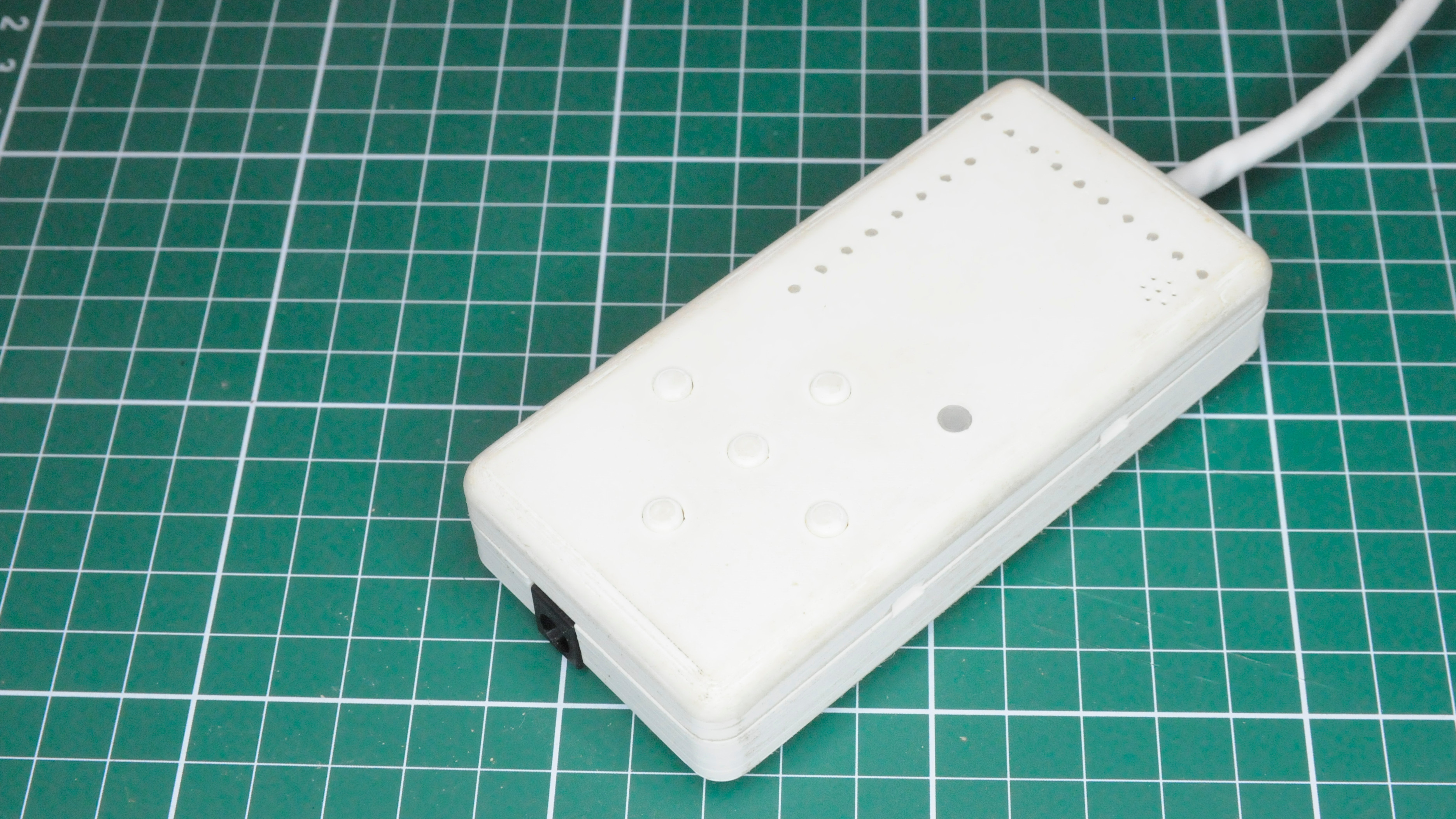
Want to print your own copy of the enclosure? It’s on my Gitlab repository.
In the next post will be writing about an attempt at firmware for the controller board.