Building The Boss
After designing the controller board, it’s now time to build it. This post will be shorter that the previous ones because there’s not too much to discuss. Spoiler: except for some issues with the power supply, all went remarkably well.
More Soldering
One more board to solder. Luckily, its not 25 this time. There is more to this board than there was with the LEDs, but it’s still very solderable by hand. Have a look at the before and after pictures below.
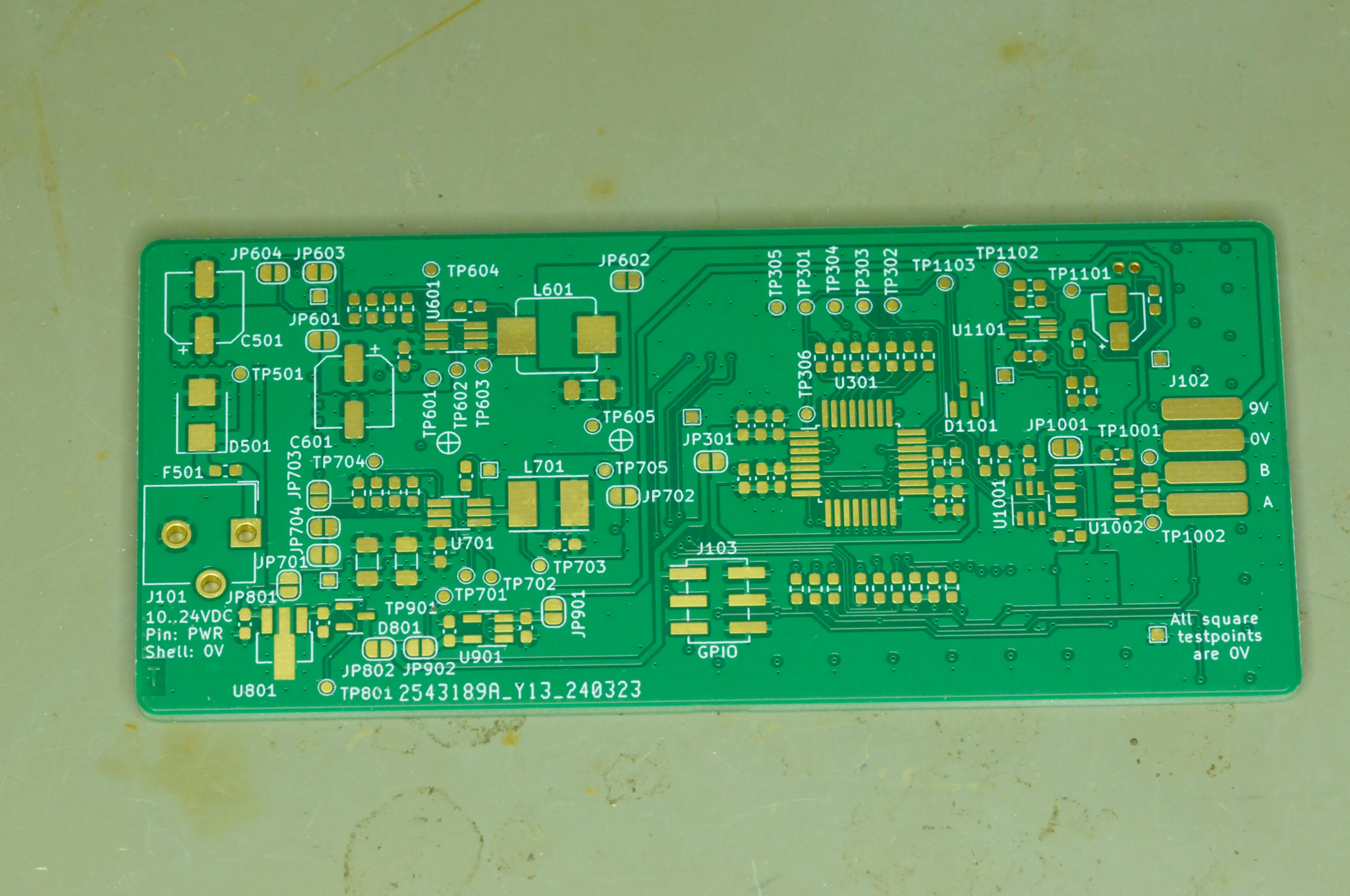 Beautiful bare board
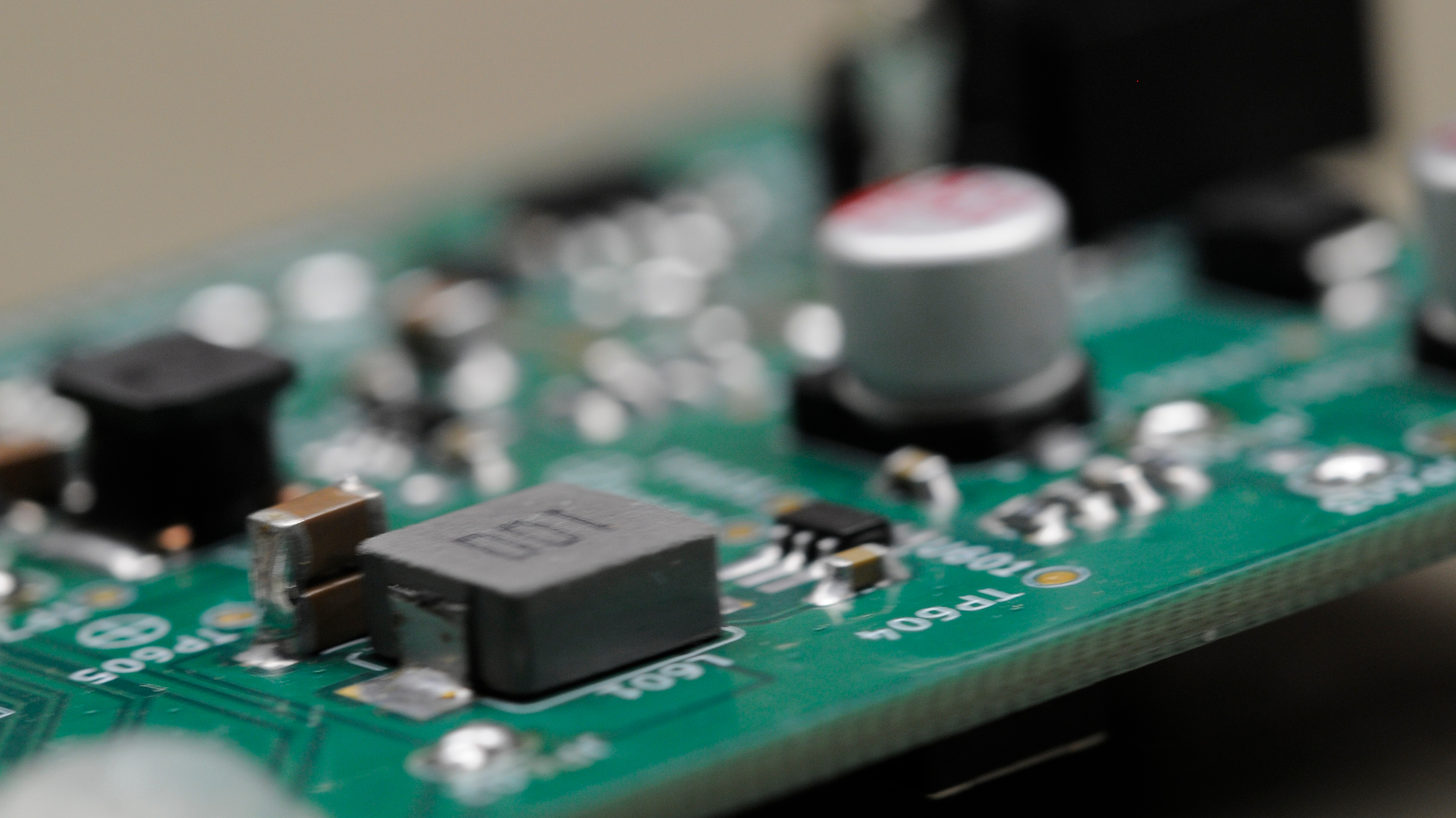
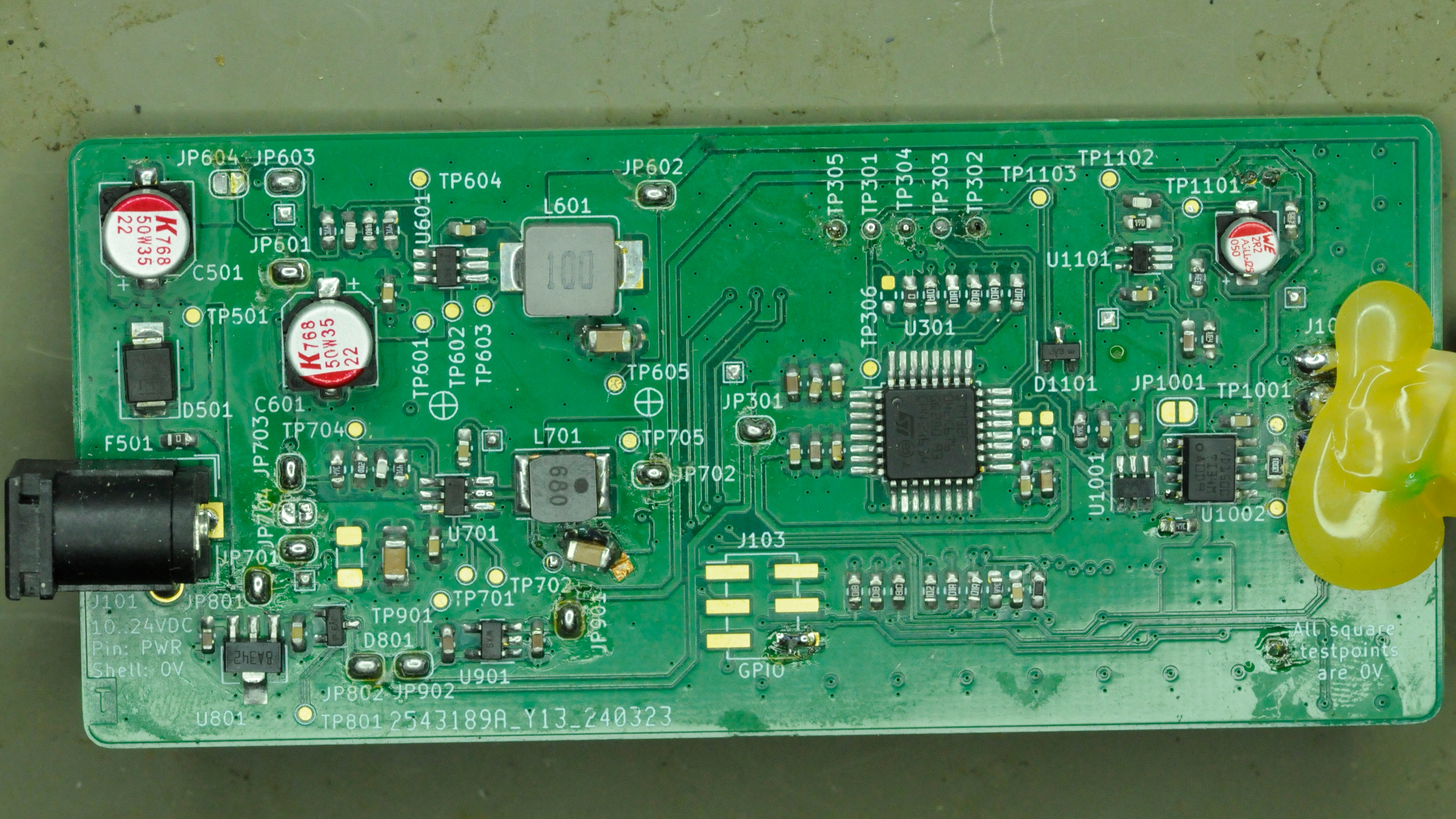 Top, populated (don’t mind the snot)
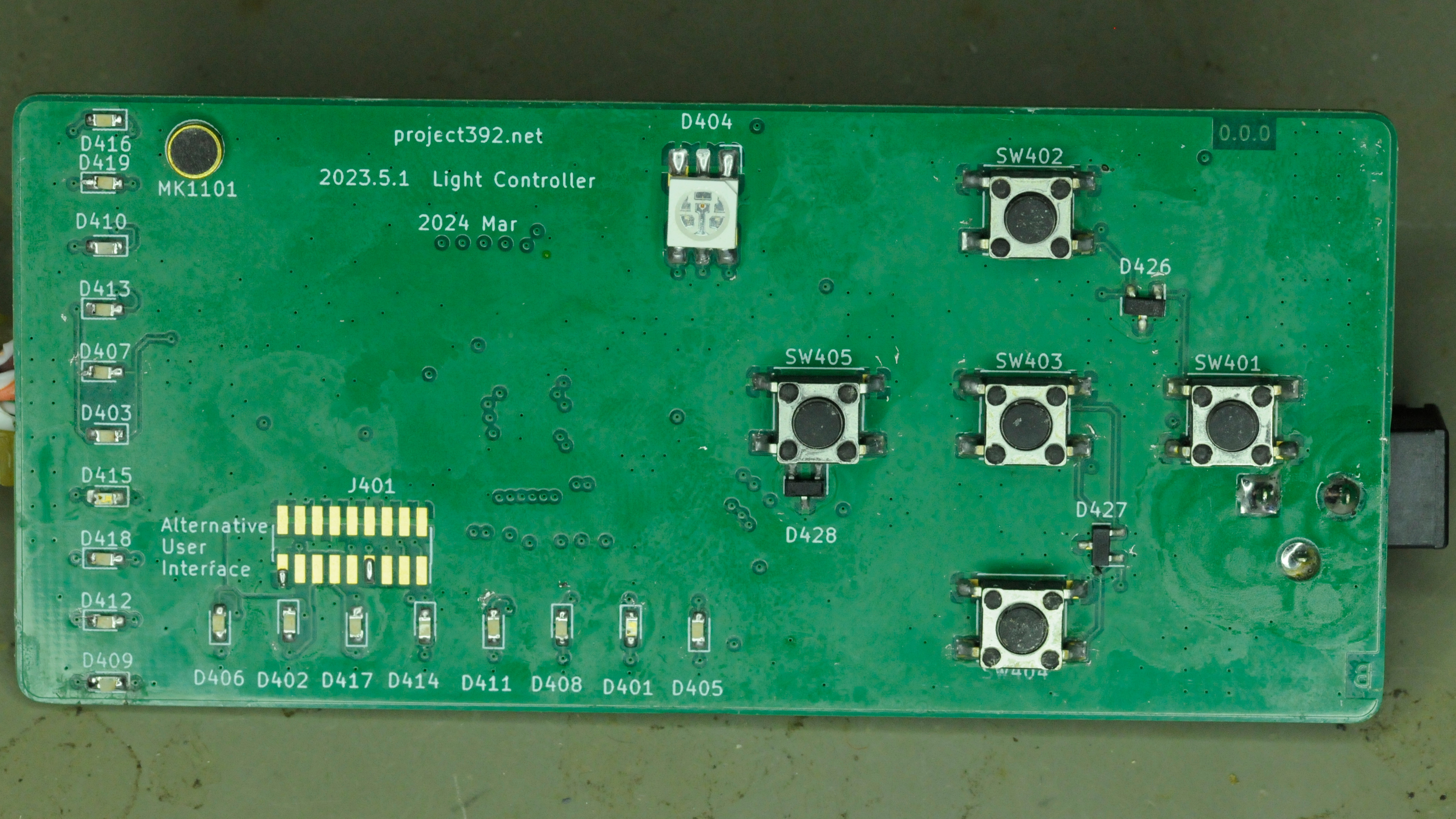 Bottom, populated
Ready? Steady? No!
Some datasheets for switching regulators give proper instructions on how to calculate the input and output capacitors. Others just give vague recommendations for what capacitors to use. Things like ‘just use two 22uF X7R capacitors and you’ll be fine’. I don’t like such recommendations and prefer a first principles approach. Rated capacitance and temperature coefficient aren’t the only parameters that matter. If you were to pick two 22uF X7R capacitors with different physical sizes, their effective capacitance would differ greatly. Even if the dimensions were identical, two capacitors from different manufacturers may not even have the same capacitance at a given DC bias.
So, instead of following the recommendations I selected the parts based on my own calculations.
That plan backfired rather badly. There turned out to be an error in my spreadsheet which led to me putting in about half the capacitance that’s needed at the output of the converter. The result: a badly instable power supply. It even emitted audible noise (which is a way for power converters to tell you that you messed up).
For the 9V supply I as able to simply stack two capacitors on top of one another to fix the problem and get a stable output voltage.
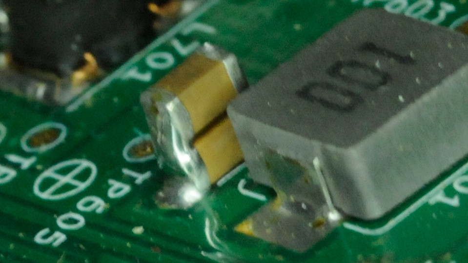 The only way is up
I wasn’t so lucky with the 5V converter however. That ended up needing a physically larger capacitor, demanding an ugly solution that involved putting a strip of copper tape on the board.
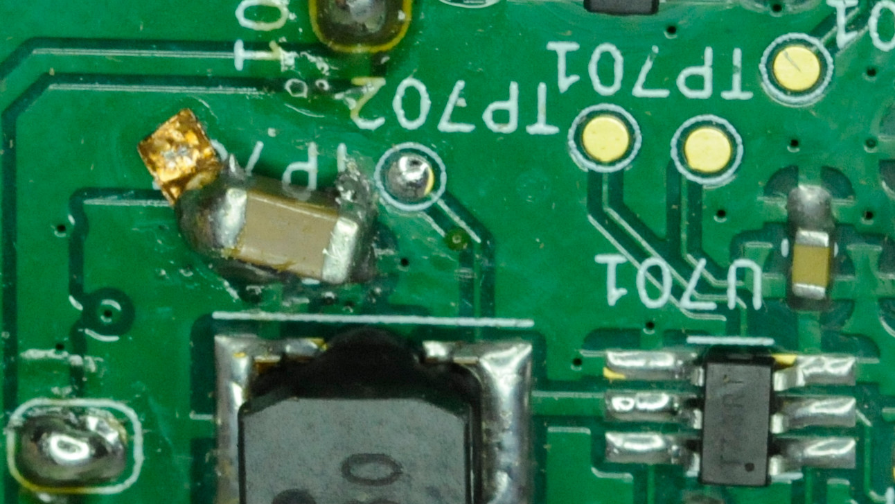 It ain’t pretty… But it works.
After this cringe-worthy fix I got two properly working voltage regulators.
A Leaky LDO
But the misery didn’t stop there for the power supply. Although the rest of the power circuit worked right away, there was another (minor) issue. As mentioned in the discussion of the LED boards, linear power supplies come in roughly two flavors: low cost (but inefficient) and moderately efficient (but more expensive). With the LED board design I choose for the low cost option due to number of boards I wanted to make.
The stand-by power supply that powers the microcontroller when its sleeping, should have been of the efficient type (with low quiescent current). For the LED boards I deliberately choose cost over efficiency. For the controller board - where there’s only one LDO regulator - I should have gone for the higher efficiency option. But I forgot and picked a low cost part there, too.
While the controller board is in sleep mode the L78L331 gently sips up to 6mA, slowly draining the battery… Unfortunately there was no easy fix for this. It would require a different type of regulator with an incompatible footprint. So with this build the power cable will have to be unplugged to save power if the device is not in use.
Can You Hear Me?
Then there’s the microphone. It’s not a key feature of the design but more a nice-to-have so I’m not going to spend too much time on it. Not until I get to implementing audio controlled features in the firmware anyway (if that ever happens).
I played a 1 khz test signal from my phone and hooked up my vintage year 2000 era DSO. This is what it showed me:
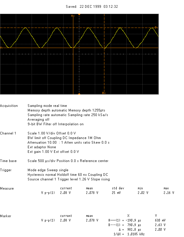
‘So tonight I’m gonna measure like it’s 1999’
Well, that’s definitely one kilohertz. The thing is that the last time I saw a sine wave up close it looked less like a triangle…
The Matrix
The LED matrix works as expected. It took a few tries to get the timing right in the firmware, but it works for now. When multiplexed the LEDs aren’t very bright so the forward current will have to be increased to some extend to make the display more visible.
Big feet
As discussed in the previous post, I wanted to make life a bit easier by extending the pads of the microcontroller footprints. This should enhance solderability (by hand). And it did. But I think I may have overdone it.
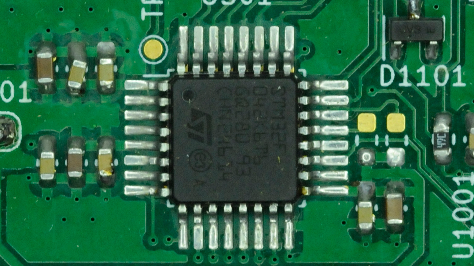 But grandmother! What big feet you have!
Next up in the series: The enclosure for the controller.